
- Introduction
- Architectural Pillar: The 9.0 vs. 9.1
- Deep Dive: The Virtual Network Appliance (VNA)Decentralizing Stateful Services
- Step-by-Step VNA Deployment Guide
- Conclusion
Introduction
VMware Cloud Foundation (VCF) 9.1 marks a definitive shift in the NSX data plane architecture. Historically, software-defined data centers relied on a Centralized Transit Gateway model where stateful services (such as NAT and Load Balancing) and inter-VPC routing were anchored to physical or virtual Edge Clusters.
While VCF 9.0 introduced the concept of the Distributed Transit Gateway (DTGW), it was constrained by a lack of stateful service support, often forcing architects back to Centralized Edges for advanced features. VCF 9.1 eliminates this architectural trade-off. By leveraging the DTGW alongside the new Virtual Network Appliance (VNA) framework, VCF 9.1 delivers complete feature parity across distributed environments—allowing traffic to stay optimized on the local hypervisor while maintaining full stateful network service compliance.
Architectural Pillar: The 9.0 vs. 9.1
To evaluate the impact of VCF 9.1, the network fabric changes must be analyzed across both Distributed and Centralized deployment models.
A. Distributed Model: VCF 9.0 vs. VCF 9.1
The primary objective of VCF 9.1 is to eliminate the stateful service gap that limited distributed mode adoption in earlier iterations.
| Technical Attribute | VCF 9.0 Distributed | VCF 9.1 Distributed (DTGW + VNA) |
| Stateful Services | Limited capabilities; required fallback to Centralized mode for advanced LB/NAT. | Full Feature Parity. Stateful NAT, Load Balancing, and DNS Forwarding are handled natively via the VNA Cluster. |
| Data Path Routing | ESXi-to-ESXi for basic routing overlays only. | Host-Local Stateful Processing via VNA + Distributed Optimization. |
| VKS Container Fabric | Standard overlay network provisioning. | Native Embedded Istio Service Mesh (Ambient mode) + Secondary Antrea NIC mapping. |
| IPAM Scalability | Rigid, basic CIDR allocation blocks. | High Density Configuration. Supports up to 10 CIDRs and 10 distinct IP ranges per Block. |
B. Centralized Model: VCF 9.0 vs. VCF 9.1
For enterprise designs requiring a Centralized Transit Gateway (CTGW) model, VCF 9.1 decouples component dependencies to deliver fault-isolated, fleet-scale resiliency.
| Technical Attribute | VCF 9.0 Centralized | VCF 9.1 Centralized (CTGW) |
| High Availability (HA) | Fate-Shared HA: The Transit Cluster Gateway (TCGW) is architecturally bound to the same Edge Nodes as the provider gateway (Tier-0/VRF), sharing HA states and physical compute resources. | Independent HA: Supports decoupled High Availability. The CTGW runs on independent, dedicated Edge Nodes with no “Fate-sharing” or resource dependencies on the provider gateway. |
| Throughput Scaling | Max capacity capped at 4-node Active-Active configurations. | 8-node Active-Active Tier-0 architecture support for doubled North-South bandwidth scale. |
| Lifecycle Operations | Linear, sequential cluster-by-cluster upgrades. | Parallel Upgrades. Orchestration support across up to 256 clusters simultaneously via SDDC Manager. |
| Fabric Provisioning | Manual greenfield parameter entry. | VPC Planning Tool automates parameter calculations by analyzing pre-existing VLAN fabrics. |
Deep Dive: The Virtual Network Appliance (VNA)Decentralizing Stateful Services
The Virtual Network Appliance (VNA) serves as the core stateful execution engine within the distributed networking framework. It enables critical services—such as Network Address Translation (NAT), Load Balancing (LB), and DNS Forwarding—for VPC workloads connected via a Distributed Transit Gateway (DTGW).
To facilitate this service delivery without relying on standard Edge Nodes, a generic traffic redirection mechanism is implemented natively within the DTGW. This mechanism intercepts and dynamically redirects qualifying stateful traffic to active nodes within the VNA cluster. For architectural resilience, a minimum of two (2) VNA nodes is recommended per cluster to establish high availability (HA), while the framework scales horizontally to support a maximum configuration of ten (10) VNA nodes per cluster.
VNA Sizing & Form Factors
| Form Factor | vCPU | RAM | Optimized For |
| Small | 2 | 4GB | Standard Dev/Test VPCs; low-concurrency NAT. |
| Medium | 4 | 8GB | Production Enterprise VPCs; Integrated Load Balancing. |
| Large | 8 | 16GB | Private AI / High-Performance DBs; heavy session counts. |
Stateful Service Injection and Packet Flow Architecture
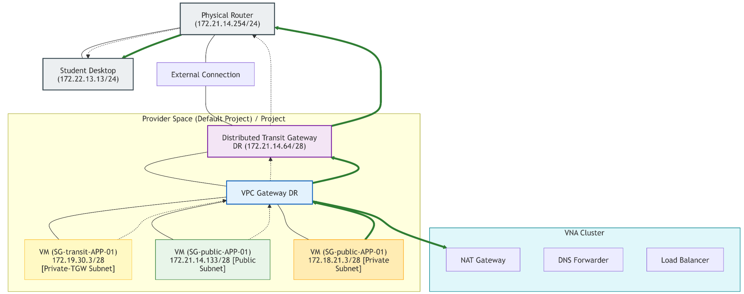
When services like LB, SNAT, DNAT, or DNS Forwarding are enabled, the VNA cluster processes the traffic inline, acting conceptually as a “Bump in the Wire.” The deterministic packet traversal path executes as follows:
- Workload Initialization: Traffic initiated by a virtual machine on a VPC subnet hits the local host’s VPC Distributed Router (DR).
- Redirection Interception: The traffic redirection policy on the DTGW evaluates the packet. If it requires a stateful service, the packet is intercepted and redirected directly to the VPC Service Router (SR) instantiated on the VNA cluster.
- Stateful Processing: The VPC SR on the VNA processes the stateful transformations (maintaining session tables, rewriting headers for NAT, or enforcing load balancing algorithms).
- Egress Hand-off: Following stateful execution, the packet flow returns from the VPC SR back to the VPC DR, which subsequently routes the deterministic traffic out through the Distributed Transit Gateway (DTGW) to the physical network fabric.
Use Cases for VNA with DTGW
- Use Case 1: vSphere Supervisor Cluster Integration: Delivers native network services for vSphere Supervisor Clusters and VCF Automation environments using an NSX VPC backed by a DTGW, enabling advanced enterprise application platforms using only simple physical VLAN prerequisites.
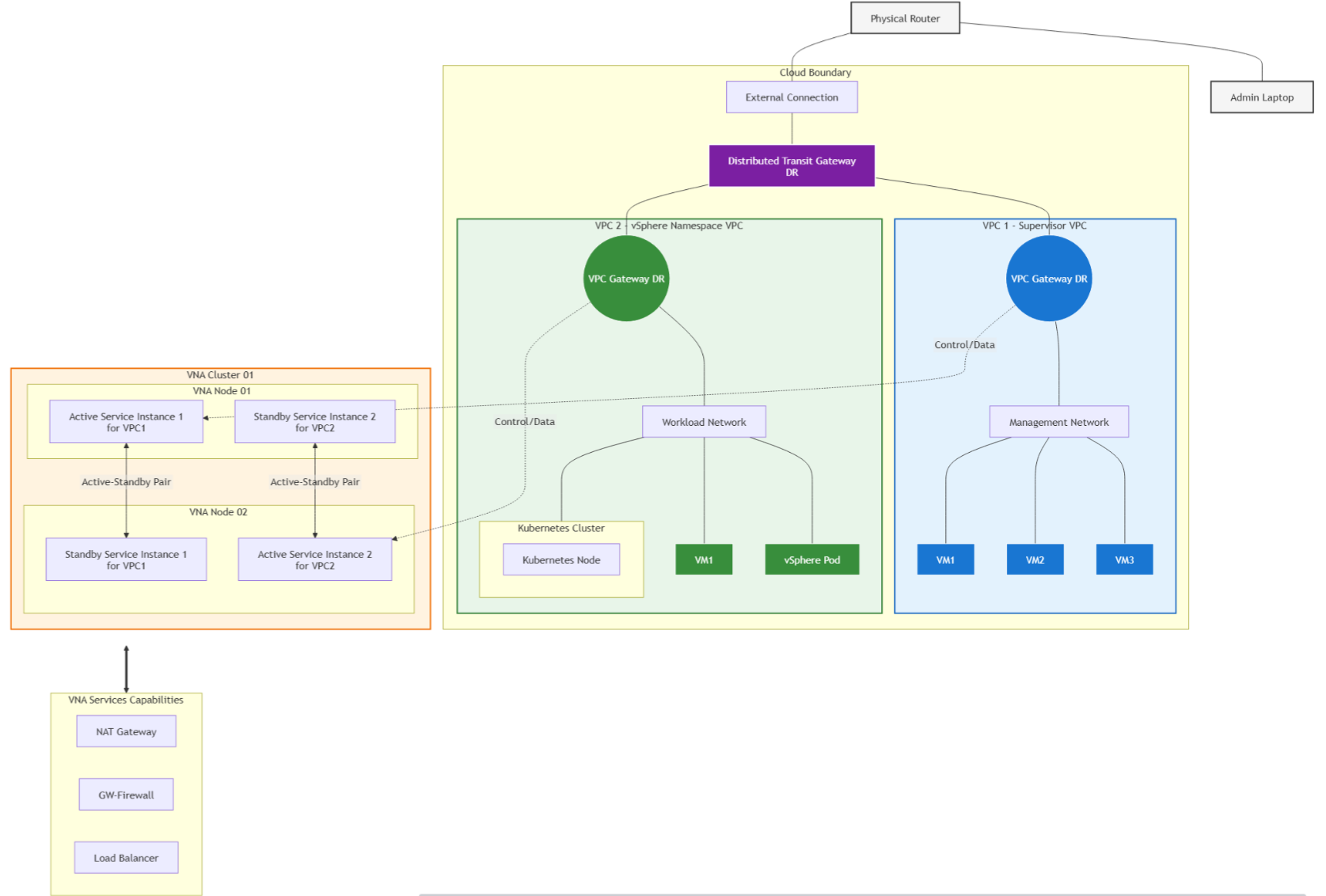
- Use Case 2: Multi-Tenant Edge-less Services: Provisions localized, isolated stateful services (NAT, Load Balancing, DNS Forwarding) directly within a distributed VPC architecture, removing centralized hardware edge dependencies and improving host-to-host performance.
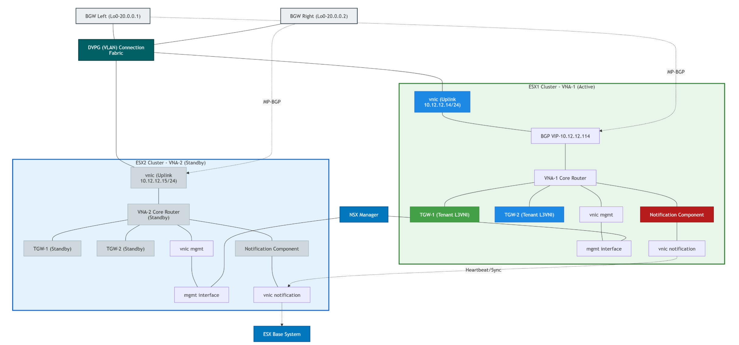
- Use Case 3: BGP-EVPN Route Control Integration: The VNA assumes the role of a VCF Route Controller within the physical BGP-EVPN VXLAN fabric overlay for the DTGW, coordinating control plane distribution and cleanly unifying virtual and physical routing layers.
Step-by-Step VNA Deployment Guide
Phase 1: Deploying the Virtual Network Appliance (VNA) Cluster
The VNA cluster must be created first before it can be assigned to any tenant or VPC. This sets up the underlying pool of virtual machines that will process stateful services (NAT, Load Balancing).
Capture 1: –
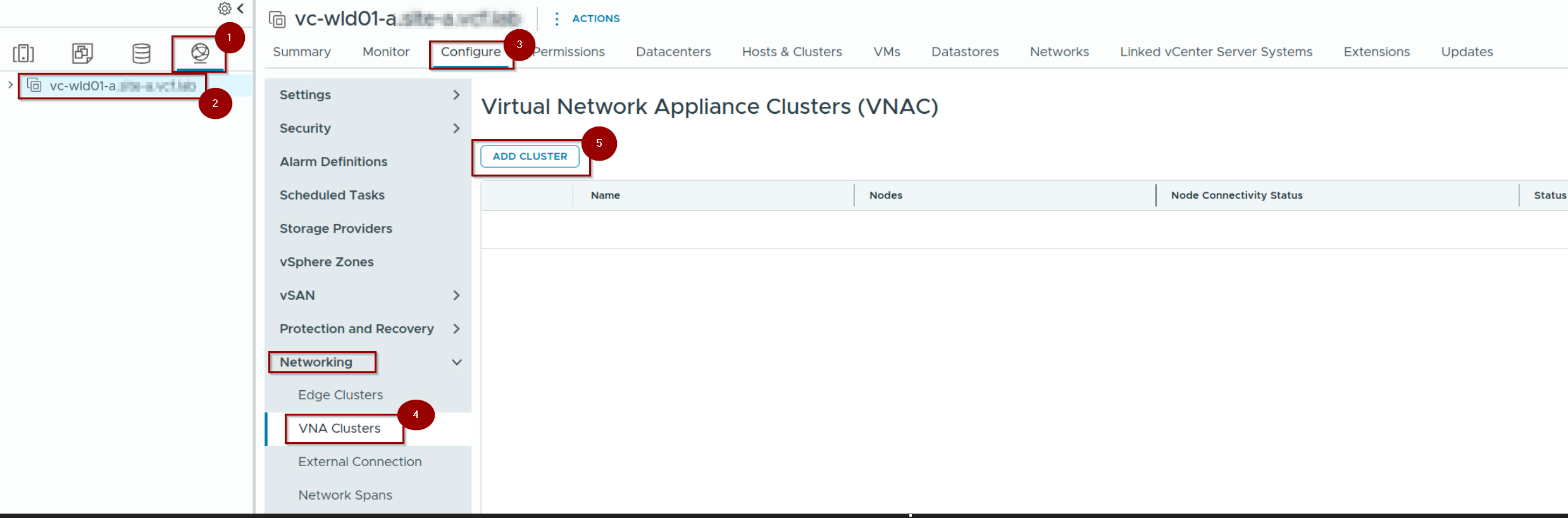
- Login to vCenter. Click on Network.
- Select the DC.
- Click on Configure.
- Under networking —> click on VNA Clusters
- Click on ADD CLUSTER.
Capture 2: –
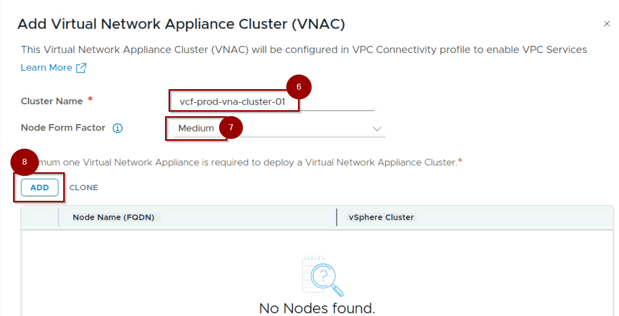
6. Give the Cluster Name.
7. Select the Node Form factor.
8. Click on ADD.
Capture 3: –
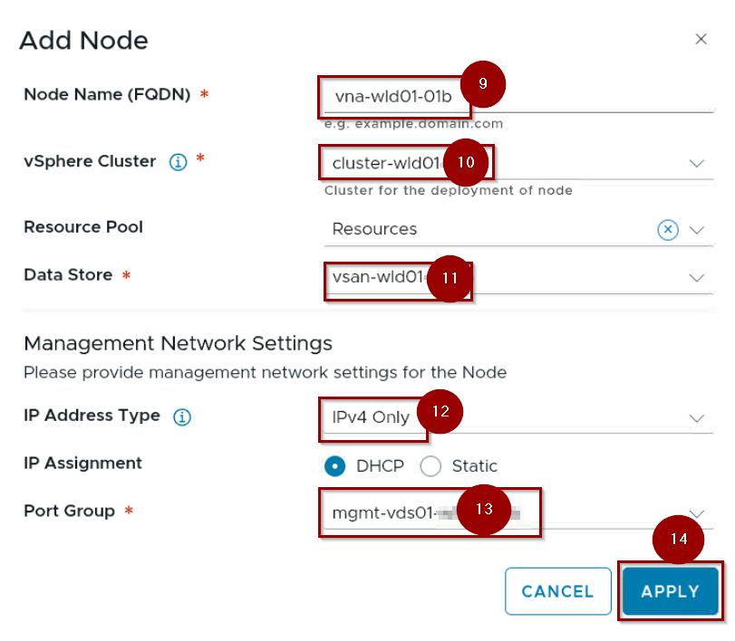
9. Give the Name of First Node.
10. Select the vSphere Cluster.
11. Select the data Store.
12. Select the IP Address Type.
13. Select the Port Group.
14. Click on Apply.
Capture 4: –
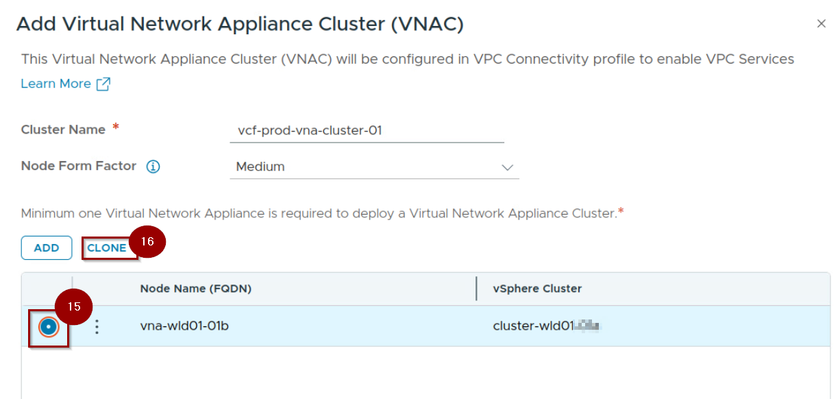
15. Select the Radio Button Infront of Node 01b.
16. Click On Clone.
Note:- Now we are installing the 2nd Node with the help of Clone method because we need to comply with the HA .
Capture 5: –
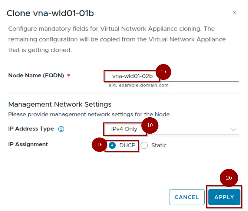
17.Give the Name of Second Node.
18. Select the IP Address Type.
19. Select the IP Assignment.
20. Click on Apply.
Capture 6: –
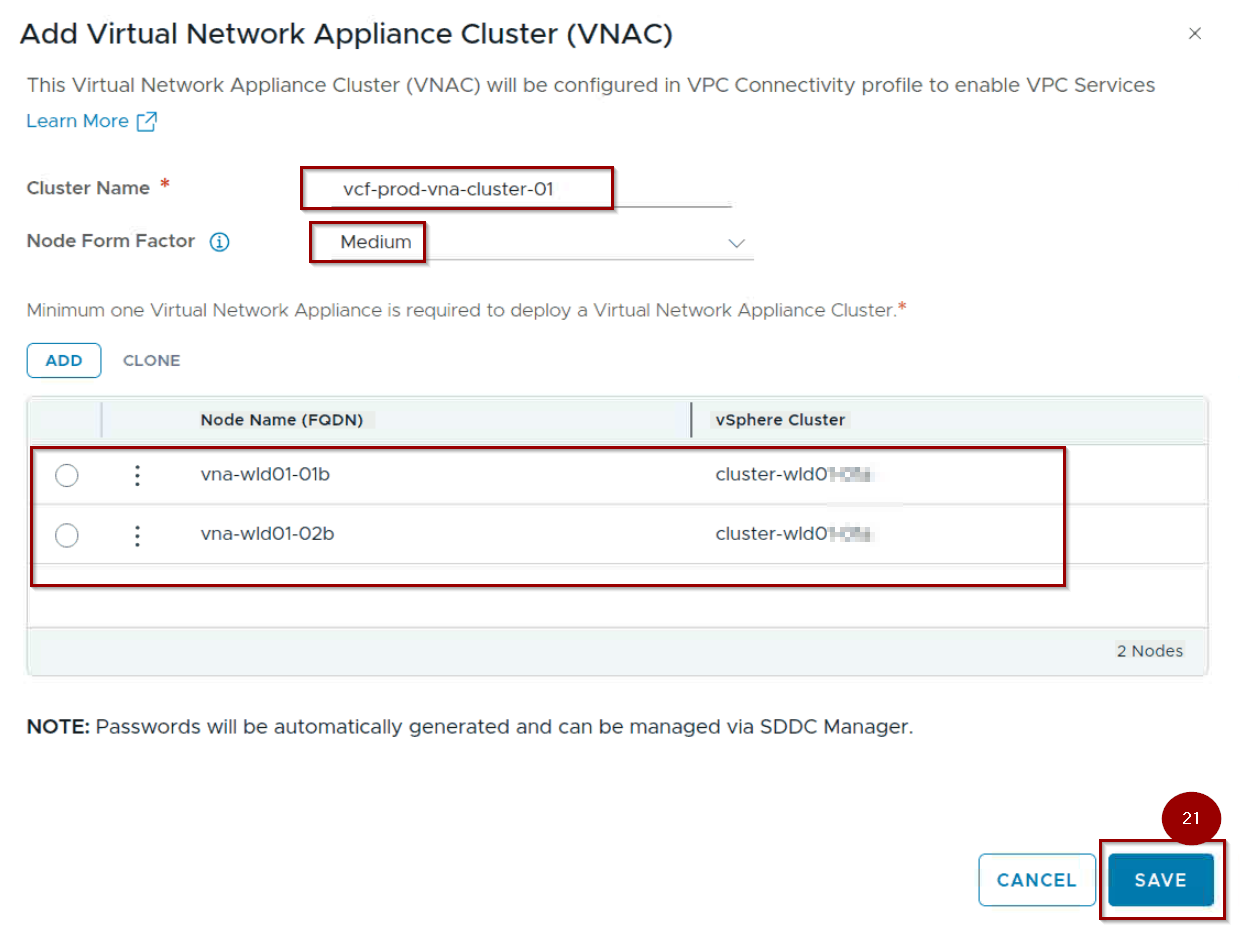
21. Click on Save.
Capture 7: –
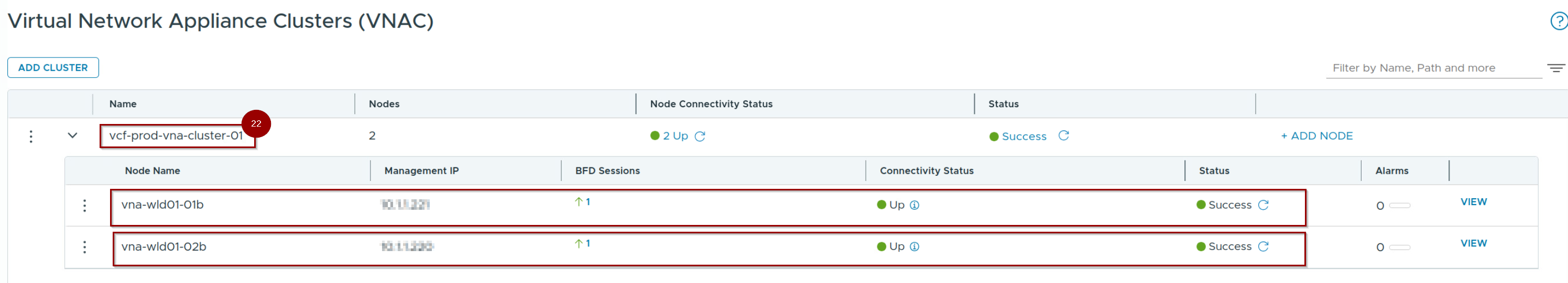
22. Nodes are successfully created and connectivity is up under the VNA cluster.
Phase 2: Connecting the VNA cluster under the Project.
Capture 1: –
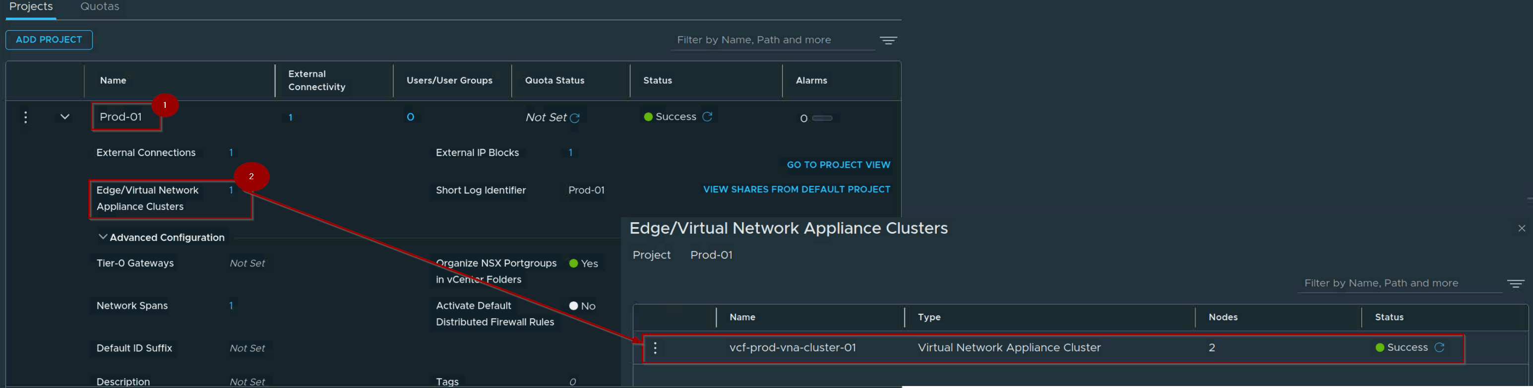
- Navigate to Project (NSX UI).
- Under Edge/Virtual Network Appliance Cluster add the VNA Cluster.
Phase 3: Connecting the Distributed Transit Gateway (DTGW)
Distributed connectivity allows you to set up VPC networking directly on the ESXi host transport nodes without relying on classic edge clusters. You link the infrastructure via a Distributed Transit Gateway.
Capture 1: –
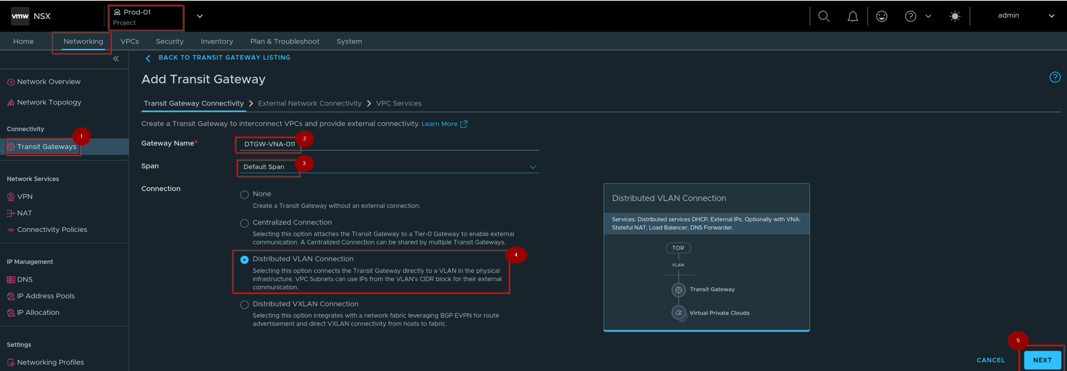
- Navigate to Your Project–> Networking—> Connectivity—> Transit Gateways.
- Give the Gateway Name.
- Select the Span.
Note:- In VCF 9.1, the concept of Span has been completely overhauled to align with the decentralized data plane.In earlier iterations, network boundaries were rigidly determined by global transport zones or edge locations. - Select the Radio button Distributed Vlan Connection.
- Click on Next.
Capture 2: –
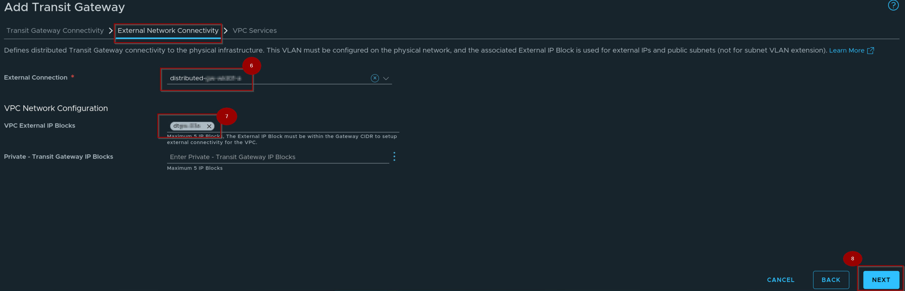
6. Select the external Connection.
7. Select the VPC External IP blocks.
8. Click on Next.
Capture 3: –
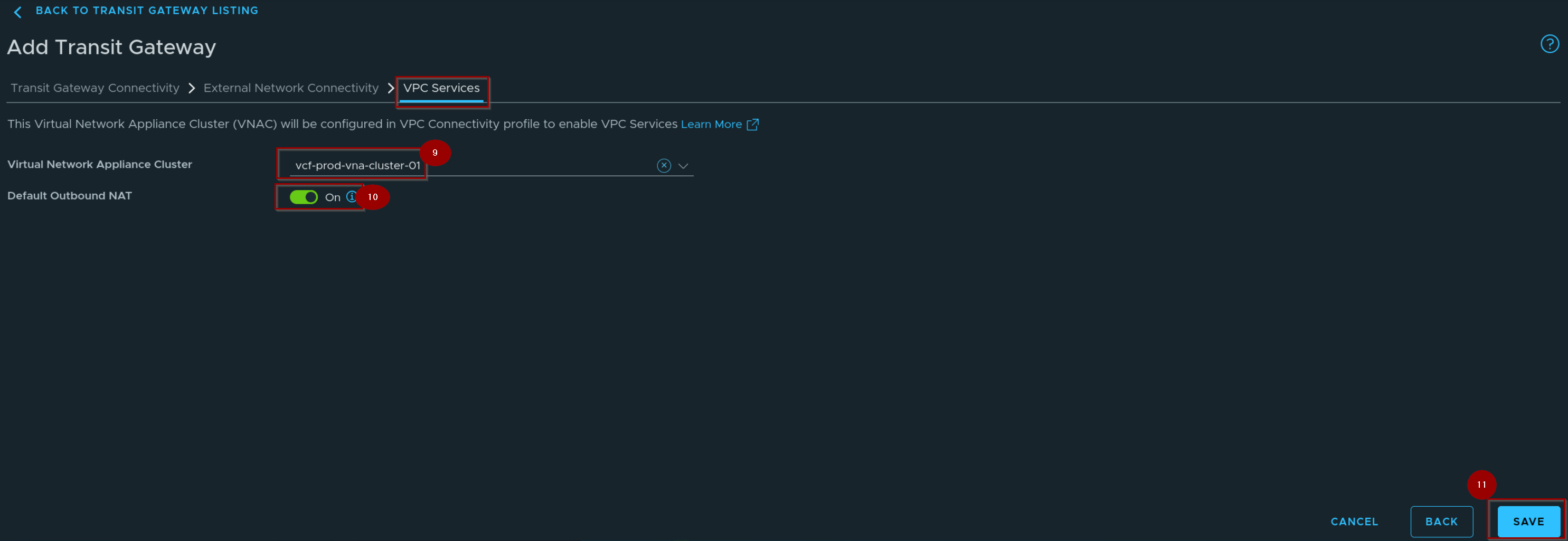
9. Select the VNA Cluster.
10. On the toggle of the Default Outbound NAT.
11. Click on Save.
Capture 4: –
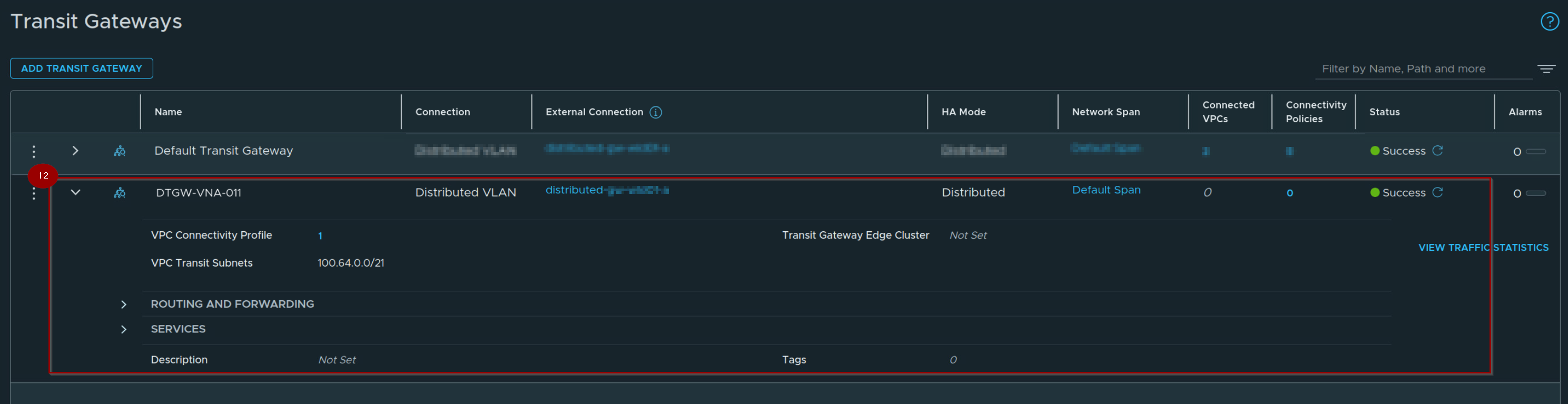
12. Transit Gateway Successfully created.
Phase 4: Attaching the VNA Cluster to the VPC Configuration
Capture 1: –
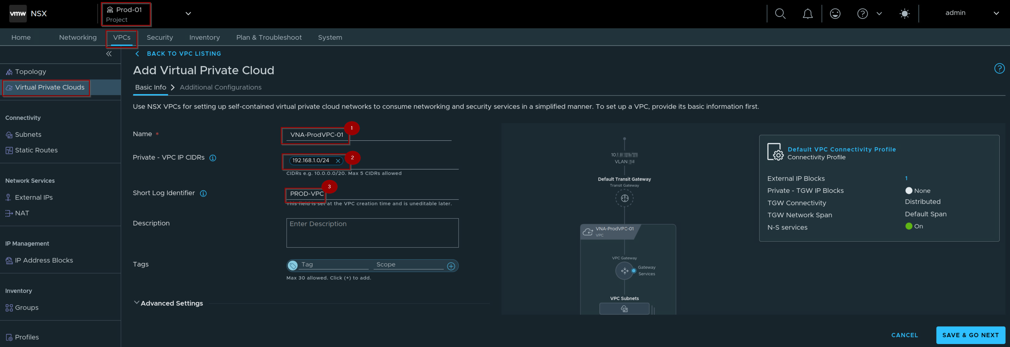
- Navigate to Your Project –> VPCs–> Virtual Private Clouds—> give the name of the VPC.
- Give the Private – VPC IP CIDRs.
- Give the Short Log identifire.
Capture 2: –
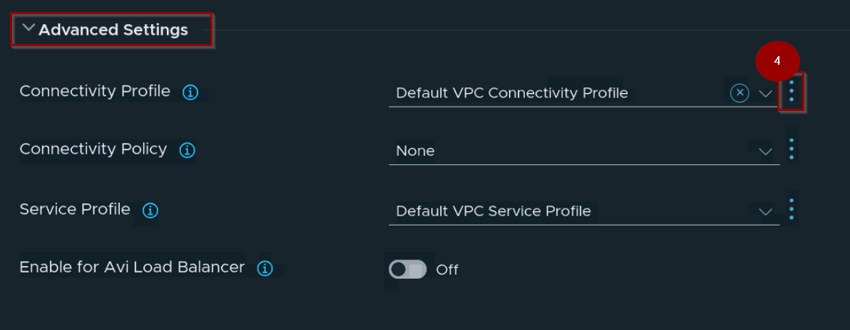
4. Navigate to Advanced Settings—> Connectivity Profile —> Click on 3 dots and click on NEW.
Note: -Deploying a new custom VPC connectivity profile instead of utilizing the default profile to ensure proper network isolation/tailored routing configurations.
Capture 3: –
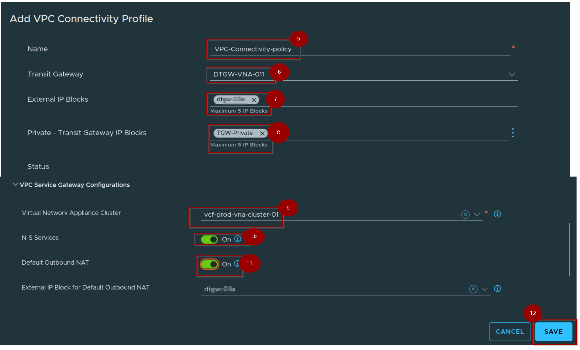
5. Give the Name of the VPC Connectivity Profile.
6. Select the transit Gateway.
7. Select the External IP Block.
8. Select the Private – Transit gateway IP Blocks.
9. Select the VNA Cluster.
10. Enable the toggle of N-S Services.
11. Enable the toggle of Default Outbound NAT.
12. Select the External Ip Block for Default Outbound NAT.
13. Click on Save.
Capture 4: –
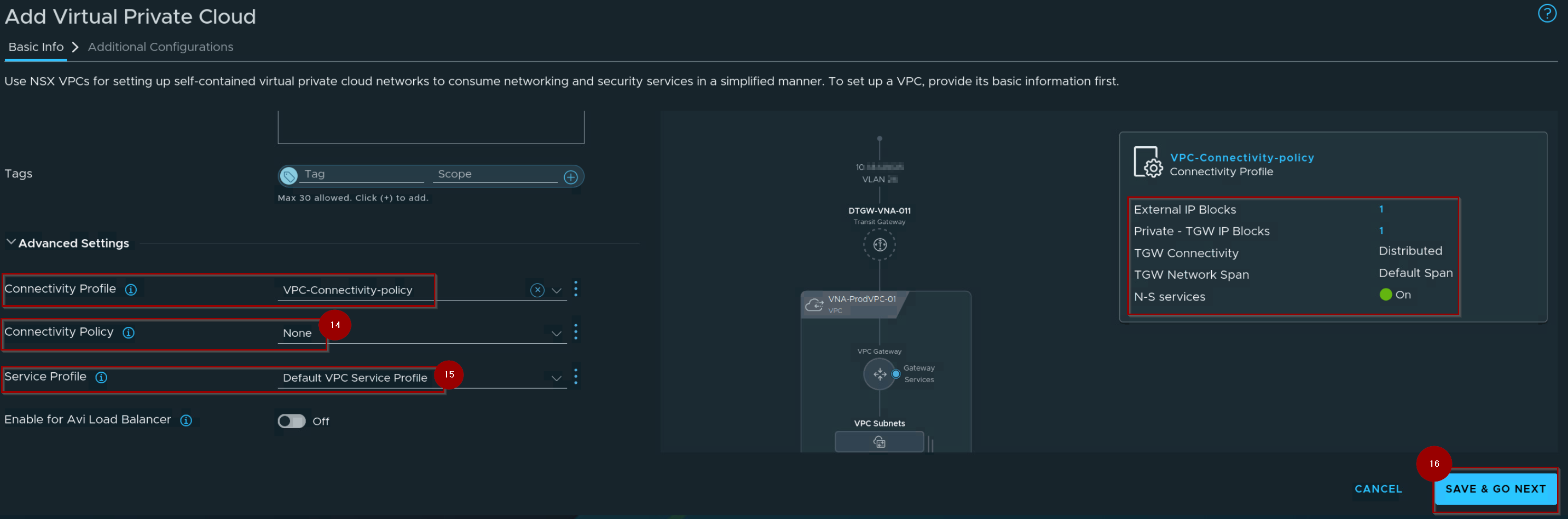
14. Select the Connectivity Policy.
15. Select the Service profile.
16. Click on Save & GO NEXT.
Capture 5: –

17. Click on YES,CONTINUE.
Capture 6: –
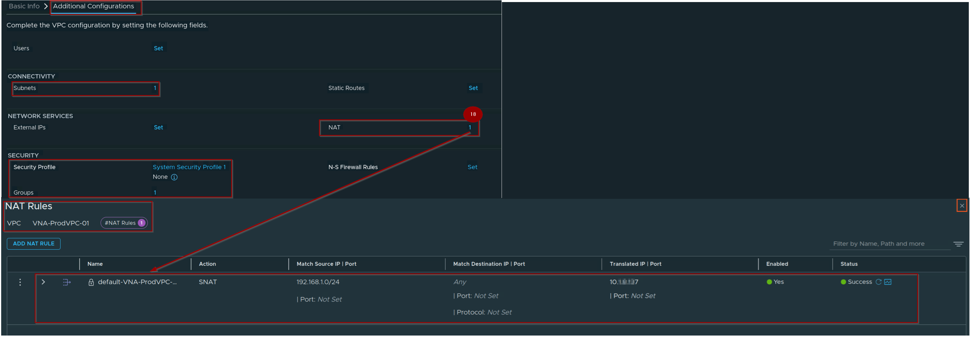
18. Validate the NAT Rule Successfully created and initialized.
Capture 7 : –
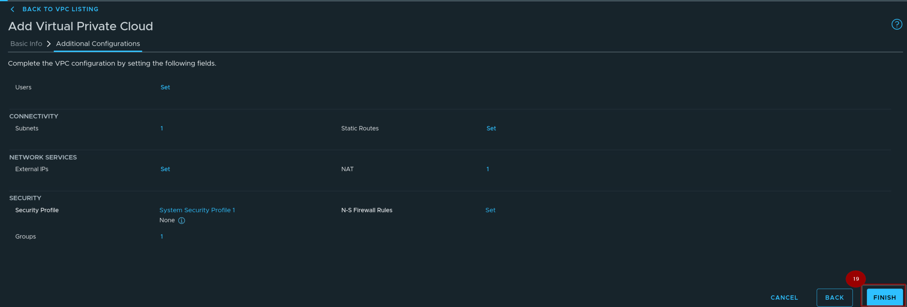
19. Click on finish.
Capture 8: –
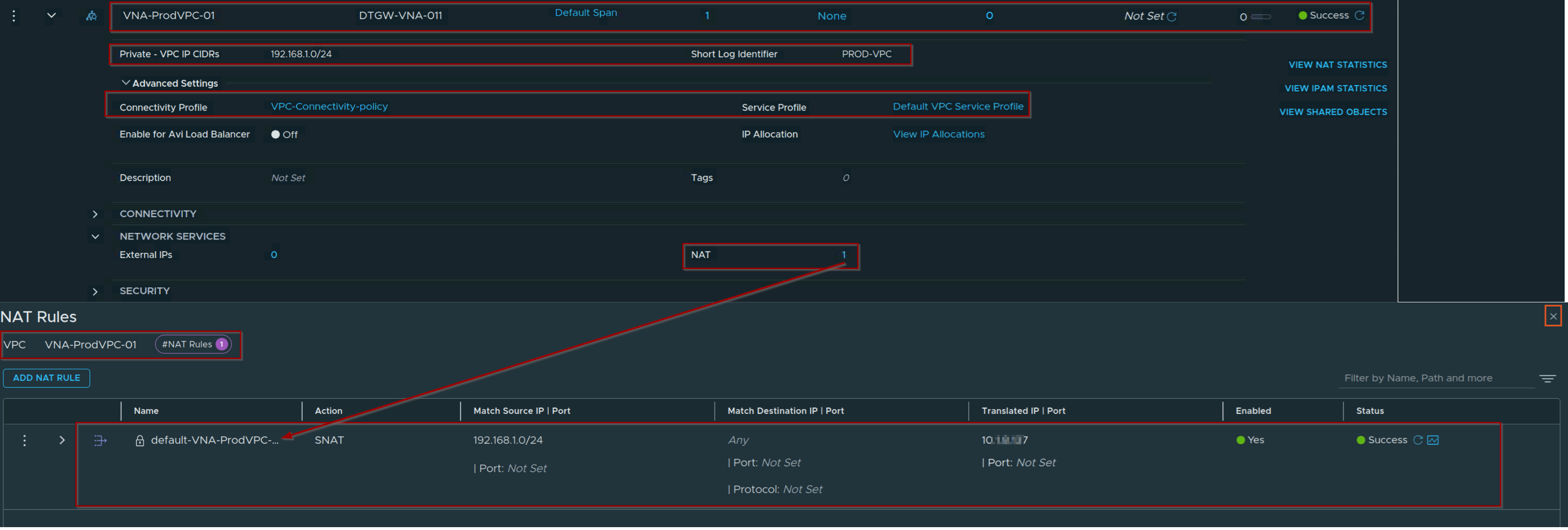
By binding the VNA (Virtual Network Appliance) cluster to the Distributed VPC, the architecture inherits stateful network capabilities, including dynamic connection tracking, stateful firewalling, and NAT services.
Capture 9: –
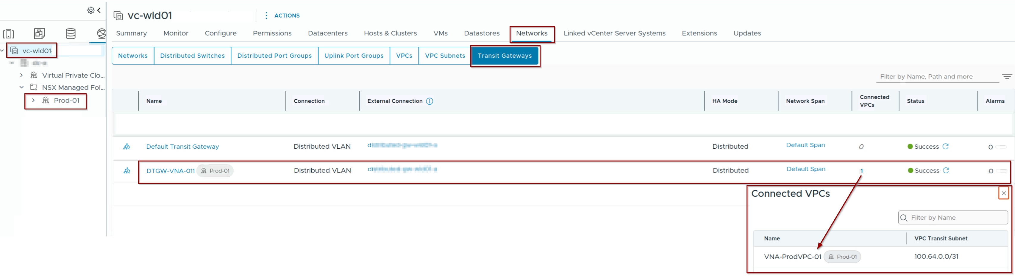
In the vCenter navigate to networks —> Transit gateways and we can verify the Project, VPC and associated Transit Distributed gateway.
Conclusion
VCF 9.1 resolves the architectural trade-off between raw performance and stateful capabilities. By pairing the Distributed Transit Gateway (DTGW) with the Virtual Network Appliance (VNA), stateful services (NAT, LB, DNS) are injected host-locally as a deterministic “Bump in the Wire.” This eliminates the sub-optimal traffic hairpinning to centralized Edge node compute blocks typical of earlier iterations.
Additionally, for centralized topologies, the transition from Fate-Shared HA to Independent HA completely decouples the Transit Cluster Gateway (TCGW) from the Provider Gateway (Tier-0/VRF) resources. This cleanly isolates fault domains and removes lifecycle dependencies, providing a highly optimized, resilient enterprise data plane.

Leave a comment