

- Introduction
- Deep Dive: Default DNAT vs. User-Defined DNAT
- DNAT Infrastructure Validation Runbook
- The Inbound DNAT CLI Verification Runbook
- Inbound Traffic Flow with Simplified topology Stack
- Step-by-Step Chronological Packet Walk
- Step 1: Ingress & Proxy ARP Resolution
- Step 2: Transit Gateway to VNA Services LIF Routing
- Step 3: VNA Stateful Firewall Engine & DNAT Translation
- Step 4: Geneve Overlay Tunnel Encapsulation
- Step 5: Compute Host Decapsulation & Subnet Delivery
- Step 6: Security Inspection & Final Delivery
- Inbound Hairpinning Mechanics (DNAT Reflection)
- DNAT Troubleshooting Quick-Reference Table
- Conclusion
Introduction
In VMware Cloud Foundation (VCF) 9.1, ingress North-South traffic targeting private VPC workload subnets traverses a Destination Network Address Translation (DNAT) boundary managed by the Virtual Network Appliance (VNA) Tier-1 Service Router (SR) context.
When external clients access published applications via public IP addresses, the VNA gateway firewall engine intercepts the ingress traffic, evaluates compiled DNAT rulesets, statefully rewrites the destination IP and port headers, and logs symmetric reverse flow entries into its connection tracking table. In Part 2 of our VNA series, we dissect the data-plane pipeline, pre/post-translation header transformations, active CLI runbooks, packet walks, hairpin reflection mechanics, and field troubleshooting tables for both Default DNAT and User-Defined DNAT.
VNA Stateful Services Series
- Part 1: Beyond get nat: Inside the VCF 9.1 VNA Architecture and Stateful NAT Data Plane
https://puneetsharma.blog/2026/07/20/beyond-get-nat-inside-the-vcf-9-1-vna-architecture-and-stateful-nat-data-plane/ - Part 2: Inbound Publishing: Architecting Default and User-Defined DNAT Pipelines (This Post)
https://puneetsharma.blog/2026/08/05/inbound-publishing-architecting-default-and-user-defined-dnat-pipelines-in-vcf-9-1-vna/ - Part 3: The VNA Bypass: Mechanics of Lateral Inter-VPC East-West Routing (Upcoming)
- Part 4: Elastic IP (EIP) Traffic vs. SVM Redirection Bypass Mechanics (Upcoming)
- Part 5: Demystifying the VNA DNS Forwarder Under the Hood (Upcoming)
- Part 6: Scaling Applications with the VNA L4/L7 Load Balancer (Upcoming
Deep Dive: Default DNAT vs. User-Defined DNAT
The VNA subsystem executes inbound destination translation through two distinct pipeline models based on allocation scope and header mapping rules:
| Architectural Attribute | Default DNAT | User-Defined DNAT |
| Data-Plane Engine | Systemic 1:1 destination mapping allocated at the boundary to bind external IP blocks directly to internal overlay endpoints. | Policy-driven pipeline matching explicit L3/L4 conditions (IP, Port, Protocol) before executing header rewrites. |
| Translation Scope | Full IP-to-IP mapping (1:1) where all ports and protocols destined for the external VIP map transparently to the internal private IP. | Granular port-forwarding (1:1 or 1:N), mapping specific public VIP/port combinations to distinct internal workload subnets or ports. |
| Operational Intent | Complete identity exposure for dedicated tenant workloads requiring full-stack inbound access without port translation. | Micro-segmented application publishing, public port remapping (e.g., Public 8080 Internal 80), and strict DMZ ingress exposure. |
| Provisioning Mode | Bound via External IP Block allocation and VPC public interface mapping declarations. | Configured manually via tenant VPC NAT Rules policies with the Action set explicitly to DNAT. |
DNAT Infrastructure Validation Runbook
Execute this runbook for infrastructure validation , compilation and connection tracking.
Discover the Infrastructure Validation
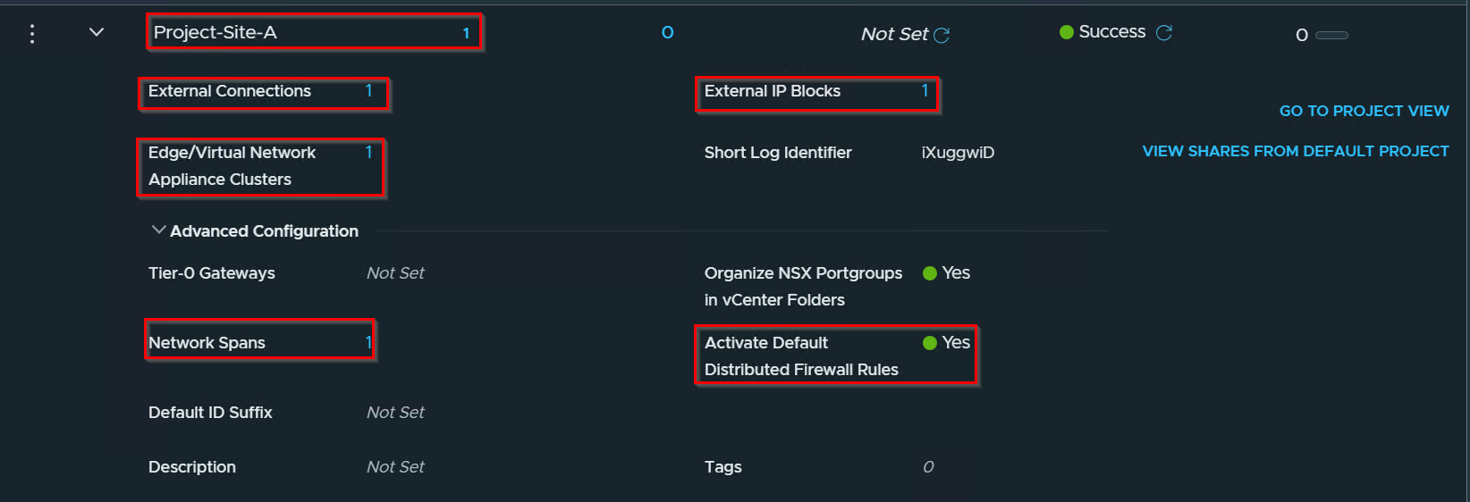
Capture 1:-
Project Validation
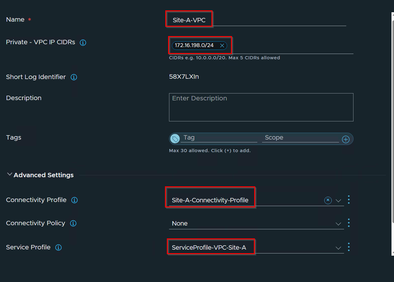
Capture 2:-
VPC Validation
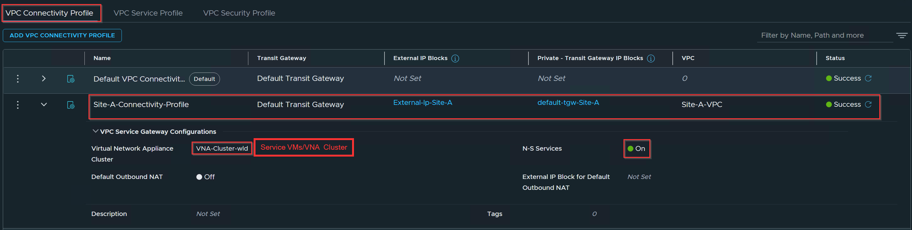
Capture 3: –
Connectivity Profile Validation
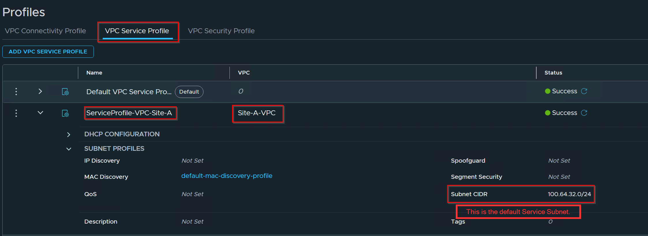
Capture 4: –
VPC Service Profile validation
Capture 5: –
DNAT Rule Validation
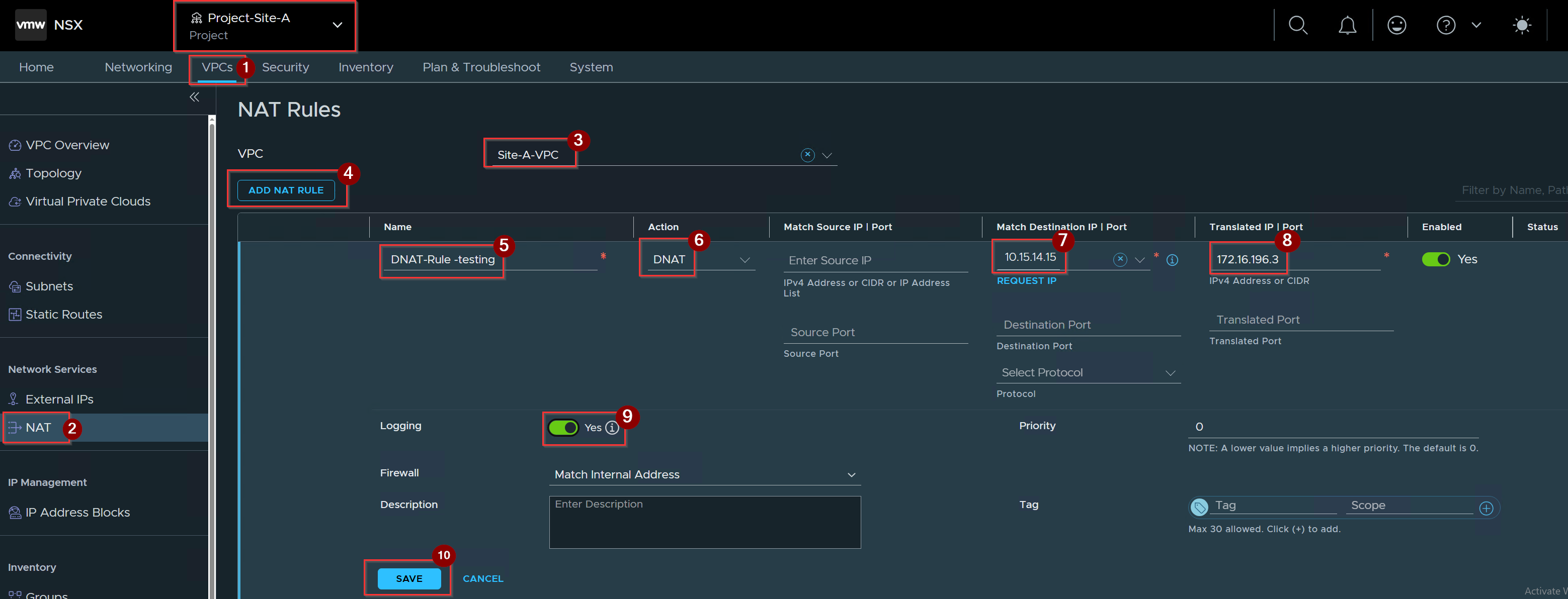
- Click on VPC Under Project.
- Click on NAT under network services.
- Select the VPC.
- Click on ADD NAT RULE.
- Give the name of DNAT rule.
- Select the DNAT under Action.
- Provide the Destination IP.
- Provide the Translated IP.
- enable the logging toggle button.
- Click on Save.
Capture 6: –
Translated VM -172.16.196.3 Validation.
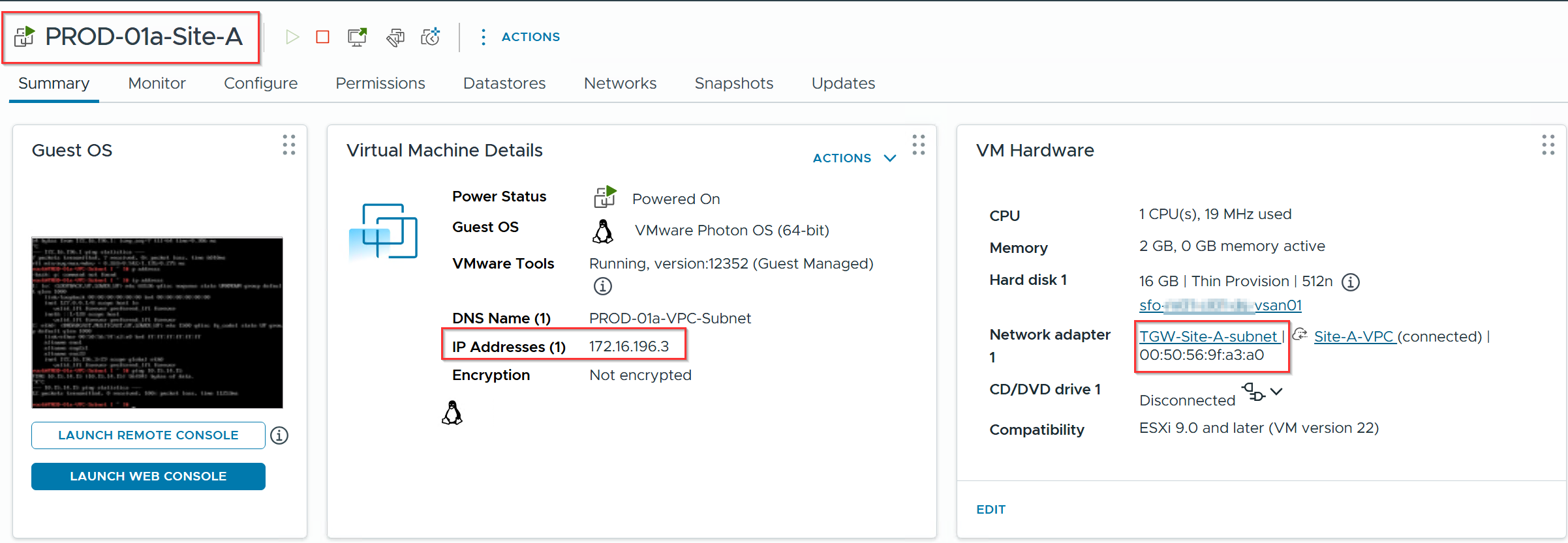
Note:- PROD-01a-Site-A VM is connected to transit gateway subnet (TGW-Site-A-Subnet).
The Inbound DNAT CLI Verification Runbook
Because DNAT rules compile directly into the VNA stateful gateway firewall memory pipeline, traditional Layer-3 routing dumps will not display active mappings. Execute this runbook on the active VNA node terminal to verify ruleset compilation and connection tracking.
Step 1: Discover Gateway UUID and Network Namespaces
Capture 1:-

cmd:- get gateways or we can use alternative cmd get vpcs
Step 2: Extract External Uplink Logical Interface (LIF) UUID
Capture 1: –
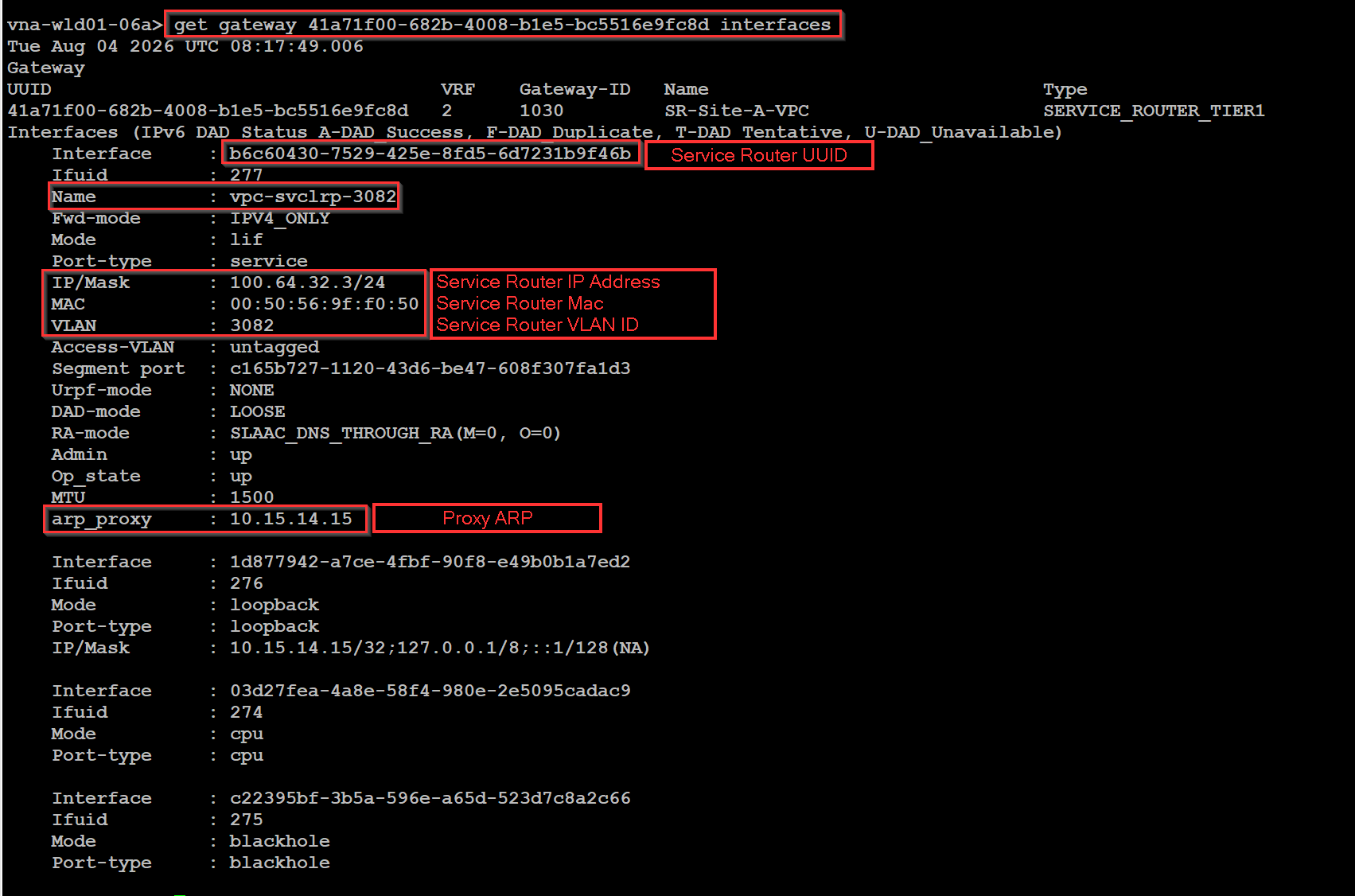
cmd :- get gateway UUID interfaces
or if you want more depth information you can use
get gateway UUID interfaces | sed '/Interface|mask|Name|Port-type|ROUTER/p
Note: – arp_proxy : 10.15.14.15, VLAN : 3082, and Segment port. Seeing arp_proxy tied directly to interface b6c60430-7529-425e-8fd5-6d7231b9f46b provides technical proof that the Service Router owns the proxy ARP binding.
Step 3: Query Programmed Inbound DNAT Rulesets
Pass the external LIF UUID into the firewall compilation parser:
Capture 1: –
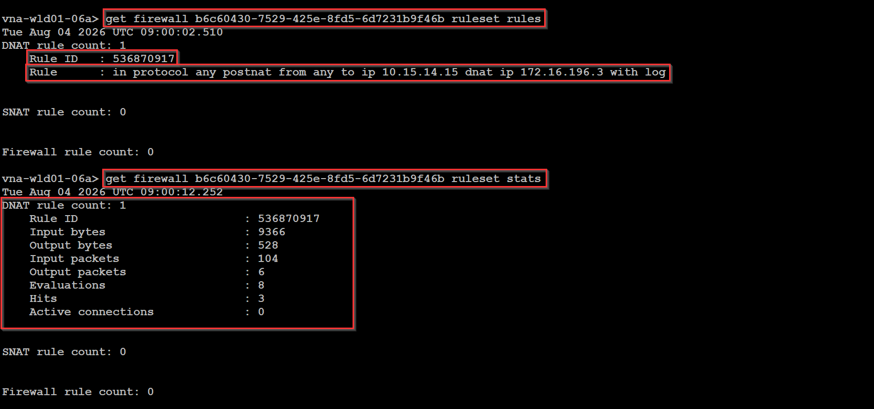
cmd :- get firewall (UUID of SVC_link) ruleset rules
Note:- This will provide you the rule id and DNAT rule info.
Cmd : – get firewall (UUID of SVC_link) ruleset stats
Note:- This cmd will provide you the Rule ID, input/output packets etc.
Step 4: Audit Real-Time Inbound Connection Tracking
Capture 1: –
Drop into the tenant VRF namespace and dump the active state table while sending inbound traffic:

cmd : – get firewall connection state
use this cmd under the VRF of the vpcs.
Data-Plane Proof: Querying get firewall returns active DNAT rulesets—this proves that in VCF 9.1, stateful NAT and perimeter firewall rules share the exact same memory-compiled pipeline inside the Tier-1 Service Router namespace rather than a traditional RIB/FIB routing table.
Inbound Traffic Flow with Simplified topology Stack
Capture 1: –
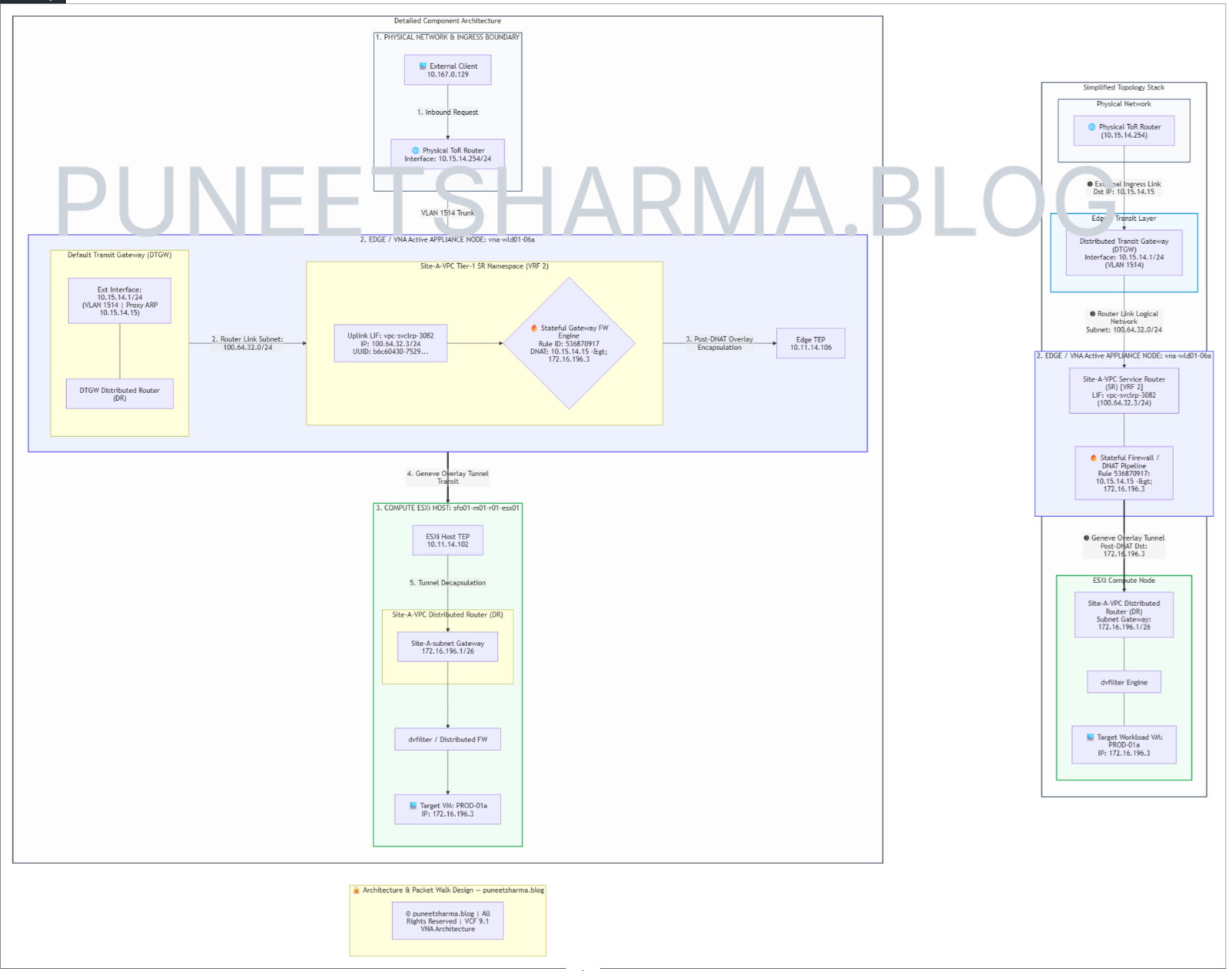
Step-by-Step Chronological Packet Walk
This packet walk traces an incoming request from the external client to the target workload VM, mapped directly to the Simplified Topology Stack callouts .
Step 1: Ingress & Proxy ARP Resolution
- Initiator: External Client (
10.167.0.129) initiates an IP packet (ICMP/TCP) targeting Public VIP10.15.14.15. - Physical Transit: The physical ToR router (
10.15.14.254) forwards the packet onto the external connection network (VLAN 1514). - Proxy ARP Handling: The Distributed Transit Gateway (DTGW) interface (
10.15.14.1) detects the packet. Because10.15.14.15is explicitly allocated toSite-A-VPC, the DTGW performs Proxy ARP, responds with its virtual MAC address, and ingresses the frame.
Step 2: Transit Gateway to VNA Services LIF Routing
- Layer: Edge / Transit Gateway Layer.
- Routing Lookup: The DTGW evaluates its routing table and matches the allocated destination VIP (
10.15.14.15) toward the transit router link network (100.64.32.0/24). - Frame Forwarding: The frame is delivered across the internal logical link directly to the Uplink Logical Interface (LIF)
vpc-svclrp-3082(100.64.32.3/24) attached to active VNA nodevna-wld01-06a.
Step 3: VNA Stateful Firewall Engine & DNAT Translation
- Layer: VNA Appliance Service Node (
vna-wld01-06a)VRF 2Context. - Rule Evaluation: The VNA Gateway Firewall engine evaluates the incoming frame on LIF
b6c60430-7529-425e-8fd5-6d7231b9f46bagainst active rulesets and matches Rule ID536870917in protocol any postnat from any to ip 10.15.14.15 dnat ip 172.16.196.3 with log - Header Rewrite:
- Pre-NAT Header:
10.167.0.129 -> 10.15.14.15 - Post-NAT Header:
10.167.0.129 -> 172.16.196.3
- Pre-NAT Header:
- Session Tracking: VNA records an active stateful entry in memory:
10.167.0.129 -> 172.16.196.3 (10.15.14.15) dir in protocol icmp f-0 n-536870917
Step 4: Geneve Overlay Tunnel Encapsulation
- Layer: VNA Edge Underlay Transport (
Edge TEP: 10.11.14.106). - Encapsulation: The post-DNAT packet (
Dst: 172.16.196.3) is encapsulated into a Geneve overlay frame with the Virtual Network Identifier (VNI) corresponding toSite-A-VPC. - Underlay Transport: The Geneve packet traverses the physical underlay fabric from Edge TEP
10.11.14.106to Compute Host TEP10.11.14.102(sfo01-WLD01-r011-esx011).
Step 5: Compute Host Decapsulation & Subnet Delivery
- Layer: ESXi Compute Host (
sfo01-WLD01-r011-esx011 - Decapsulation: Host TEP
10.11.14.102receives the Geneve frame, strips the underlay headers, and delivers the inner Ethernet payload to theSite-A-VPCDistributed Router (DR). - Local Subnet Routing: The DR routes the packet onto
Site-A-subnet(172.16.196.0/26) via default gateway172.16.196.1.
Step 6: Security Inspection & Final Delivery
- Layer: Hypervisor Port Filter (
dvfilter) Workload vNIC. - Firewall Filter: The packet passes through the Distributed Firewall (
dvfilter) policy layer attached to the VM switch port. - Workload Delivery: The translated packet arrives at
PROD-01a(172.16.196.3), which processes the request and generates a return packet destined back to10.167.0.129.
Inbound Hairpinning Mechanics (DNAT Reflection)
Hairpinning occurs when an internal tenant VM (VM-A: 172.16.196.4) accesses a peer workload (VM-B: 172.16.196.3) using VM-B’s public VIP (10.15.14.15:8080) rather than its internal overlay IP.
| Step | Processing Stage | Node / Boundary | Packet Transformation (Src → Dst) |
| 1 | Egress Intercept | VM-A (172.16.196.4) –>DR | 172.16.196.4:49152 —> 10.15.14.15:8080 |
| 2 | Double Translation | VNA Engine (VRF 2) | DNAT: 10.15.14.15:8080 —> 172.16.196.3:80SNAT: 172.16.196.4 —> 100.64.32.3 |
| 3 | Stateful Delivery | VNA —> VM-B (172.16.196.3) | 100.64.32.3:49152 —> 172.16.196.3:80 |
| 4 | Symmetric Return | VM-B —>VNA —>VM-A | Un-SNAT: 100.64.32.3 —-> 172.16.196.4Un-DNAT: 172.16.196.3:80—> 10.15.14.15:8080 |
Egress Intercept: VM-A sends a frame to 10.15.14.15:8080. The local hypervisor Distributed Router (DR) identifies 10.15.14.15 as external and encapsulates the packet via Geneve overlay to active node vna-wld01-06a.
Double Translation (DNAT + Reflective SNAT): The VNA firewall engine executes DNAT (10.15.14.15:8080 —> 172.16.196.3:80). Simultaneously, VNA executes Reflective SNAT (172.16.196.4 –> 100.64.32.3), preventing VM-B from sending an un-translated L2 reply directly to VM-A, which would bypass connection tracking and drop the TCP session.
Stateful Ingress Delivery: VNA delivers the double-translated frame to VM-B. Return traffic from VM-B is forced back to VNA first, ensuring symmetric connection tracking un-translation before returning to VM-A.
DNAT Troubleshooting Quick-Reference Table
| Inbound Failure Symptom | Underlying Root Cause | Verification Command on Active VNA Node |
External client times out (SYN_SENT); zero state entries created. | Inbound firewall rule uncompiled or LIF UUID bound incorrectly. | get firewall <LIF-UUID> ruleset rules |
Connection state shows dir inbound but client receives TCP RST. | Destination port translation mismatch or application service down on internal VM. | vrf <VRF-ID> get firewall connection state |
| Hairpin traffic fails between internal VMs using public VIP. | Reflective SNAT omitted; return traffic bypassing VNA via local DR East-West path. | get firewall <LIF-UUID> ruleset rules (Verify reflection rule compilation) |
| Extract External Uplink Logical Interface (LIF) UUID | This will provides technical proof that the Service Router owns the proxy ARP binding. | |
Conclusion
Publishing internal workload services via VNA Inbound Destination NAT (DNAT) demands seamless alignment across edge transit gateways, stateful firewall rulesets, and Geneve overlay encapsulation pathways. By evaluating pre- and post-translation packet header transformations alongside VRF-isolated firewall state tracking utilities, network architects and engineers can deterministically validate, audit, and troubleshoot North-South ingress traffic within VCF 9.1 multi-tenant VPC environments.
In the next installment—Part 3: The VNA Bypass: Mechanics of Lateral Inter-VPC East-West Routing—we will explore how VCF 9.1 bypasses stateful service appliances to deliver line-rate, hypervisor-distributed routing between isolated tenant VPCs.


Leave a comment