

Introduction
VMware Cloud Foundation (VCF) 9.1.1 expands Virtual Private Cloud (VPC) capabilities by offering VLAN-backed VPC Subnets in TEP-less Mode. Traditional NSX overlay networks rely on Geneve tunneling, requiring Host Tunnel Endpoints (TEPs), dedicated IP pools, and an MTU of 1600+ across the underlay. In contrast, TEP-less VLAN-backed VPCs extend tenant multi-tenancy and project isolation directly over standard 802.1Q physical VLANs.
This guide explores the underlying packet architecture, breaks down key configuration parameters, provides side-by-side technical comparisons, and delivers a step-by-step operational walkthrough to configure TEP-less VLAN-backed VPCs.
Understanding TEP-Less Architecture and Packet Flow
In standard NSX overlay VPCs, the hypervisor encapsulates VM egress traffic inside an outer UDP/Geneve header. The source host de-constructs the logical frame, wraps it with a Host TEP source IP and target TEP destination IP, and sends it across the physical fabric.
In TEP-less Mode, ESXi hosts do not require host TEP interfaces, TEP IP pools, or Geneve encapsulation capabilities. Instead, multi-tenant VPC subnets leverage standard hardware-level VLAN tagging on the Distributed Virtual Switch (VDS).
End-to-End Architectural Diagram

Step-by-Step Traffic Lifecycle
Egress Initiation (Guest OS to Port Group): Tenant PROD-VM (IP: 10.15.14.x) generates an IP packet (e.g., an ICMP Echo Request to physical default gateway 10.15.14.1). The frame exits the virtual vNIC unencapsulated and arrives at the NSX VPC L2 Subnet Port.
Hypervisor Tagging (VDS Processing): Rather than appending a Geneve overlay wrapper, the Distributed Virtual Switch (VDS) applies an IEEE 802.1Q tag for VLAN 1514 directly to the Ethernet frame based on the TEP-less VPC subnet backing.
Physical Uplink Egress: The tagged 802.1Q frame exits the ESXi host via physical uplinks (vmnic0/vmnic1) across an 802.1Q trunk port to the physical network fabric.
Physical Line-Rate Switching: The Top-of-Rack (ToR) switch receives the frame on VLAN 1514 and switches it at line rate across the internal switch fabric directly to the Layer 3 Core Router / Switch Virtual Interface (SVI).
Physical Gateway Processing & Ingress Return: The physical default gateway SVI (10.15.14.1) processes the packet and issues an ICMP Echo Reply. The reply frame travels back across the ToR switch on VLAN 1514, enters Host 1’s physical uplink, and reaches the VDS. The VDS strips the 802.1Q tag and delivers the raw frame back to PROD-VM.
Architectural Comparisons
Host Preparation: Configure Networking vs. Configure NSX (Advanced)
When preparing host clusters for NSX and VCF 9.1 VPC capabilities, administrators are presented with two distinct UI workflows inside the vSphere Client.
| Comparison Vector | Configure Networking | Configure NSX (Advanced) |
| Primary Operational Model | VCF Profile & Policy-Driven: Uses declarative vSphere Configuration Profiles (VCP) and automated SDDC Manager abstractions. | Traditional NSX Transport Node Profile (TNP): Requires manual, parameter-by-parameter binding of TNPs, Uplink Profiles, and N-VDS settings. |
| Management Authority | vCenter / VCF Lifecycle Management governs host networking profiles natively. | NSX Manager directly controls host networking configurations. |
| Network Span Support | Native Integration: Allows assigning clusters directly to Network Spans (including TEP-less Spans) directly from vSphere Client. | Clusters managed via advanced profiles cannot be bound to Network Spans via vSphere Client wizards. |
| Target Use Case | Modern VCF 9.0/9.1 automated deployments, VPC abstractions, and simplified cluster onboarding. | Custom host configurations, legacy NSX clusters, non-standard pNIC mappings, or complex multi-N-VDS designs. |
Network Spans: Exclusive Span Enabled vs. Exclusive Span Disabled
Network Spans define the cluster scope across which VPC resources, transit gateways, and subnets can be provisioned. The Exclusive Span toggle determines resource isolation across spans.
| Feature Scope | Exclusive Span Enabled (Yes) | Exclusive Span Disabled (No / Default) |
| Cluster Allocation | Dedicated Assignment: Clusters assigned to an Exclusive Span are locked to that specific span. | Shared Assignment: Clusters can be shared across multiple overlapping Network Spans. |
| Multi-Tenancy Isolation | Strict Hard Isolation: Prevents other projects or global network scopes from consuming compute resources on these clusters. | Flexible Allocation: Allows common compute clusters to host subnets from multiple general-purpose network spans. |
| VPC & Transit Gateway Scope | Limits VPC boundaries strictly to the dedicated cluster hardware boundary. | Allows VPCs to span broadly across general multi-cluster environments. |
| Primary Recommended Use Case | Dedicated tenant clusters, high-security workload domains, or dedicated TEP-less edge/compute zones. | General-purpose enterprise clouds, shared infrastructure domains, and flexible multi-department pools. |
Step-by-Step Configuration Guide
Step 1: Create a TEP-Less Network Span in vCenter
Capture 1: –
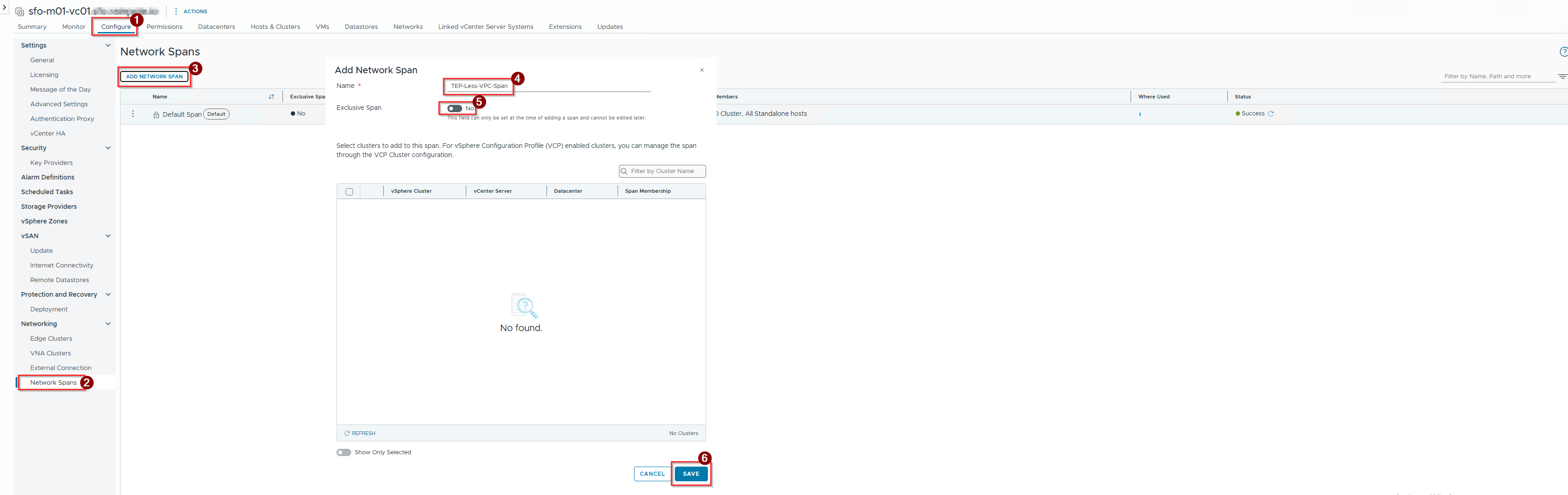
- Click on Configure.
- Click on Network spans under Networking.
- Click on ADD NETWORK SPAN.
- Give the name of the TEP less span.
- Exclusive span toggle should be No.
- Click on Save.
Note:- Keep Exclusive Span set to No if your compute cluster needs to participate in other shared spans. Switch to Yes if you are dedicating the host cluster exclusively to this TEP-less VPC boundary and want to prevent it from joining any other Network Span.
Capture 2: –
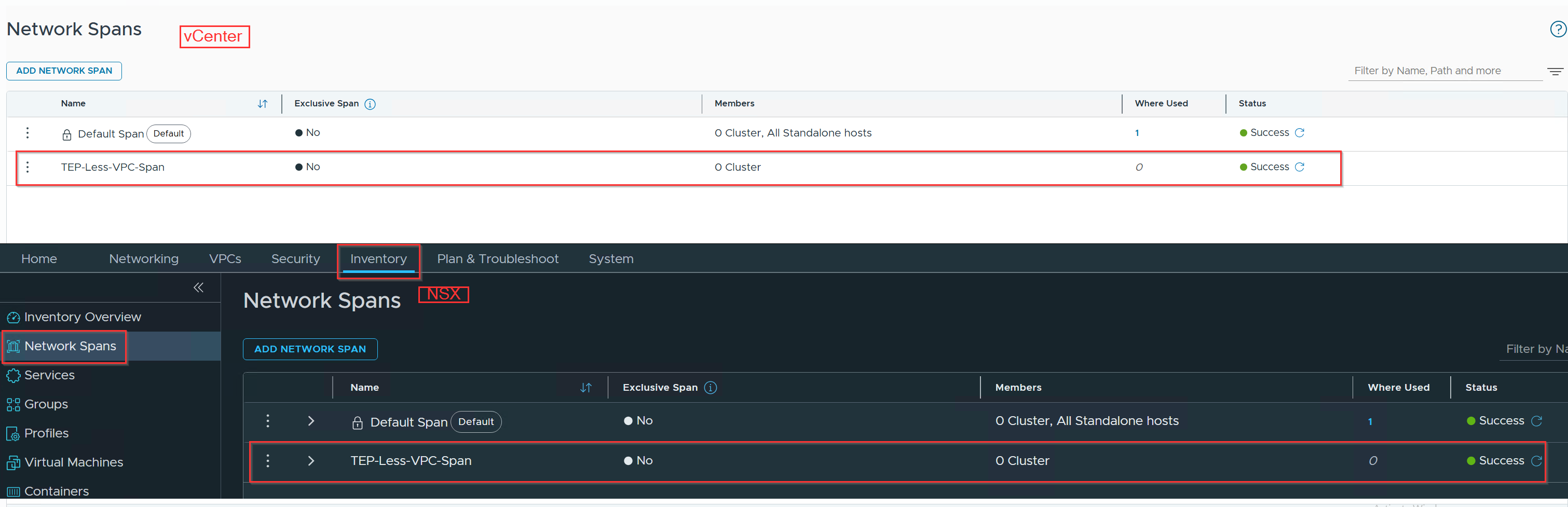
We can validate that the TEP-Less-VPC-Span is successfully created in vCenter and is also appearing in NSX.
Step 2: Create a TEP-Less TNP and Prepare the Host Cluster
To enable TEP-less mode, the host cluster must be bound to a Transport Node Profile (TNP) configured without TEP interfaces, alongside the Network Span created in Step 1.
- Create the TEP-Less Transport Node Profile:
Capture 1:-
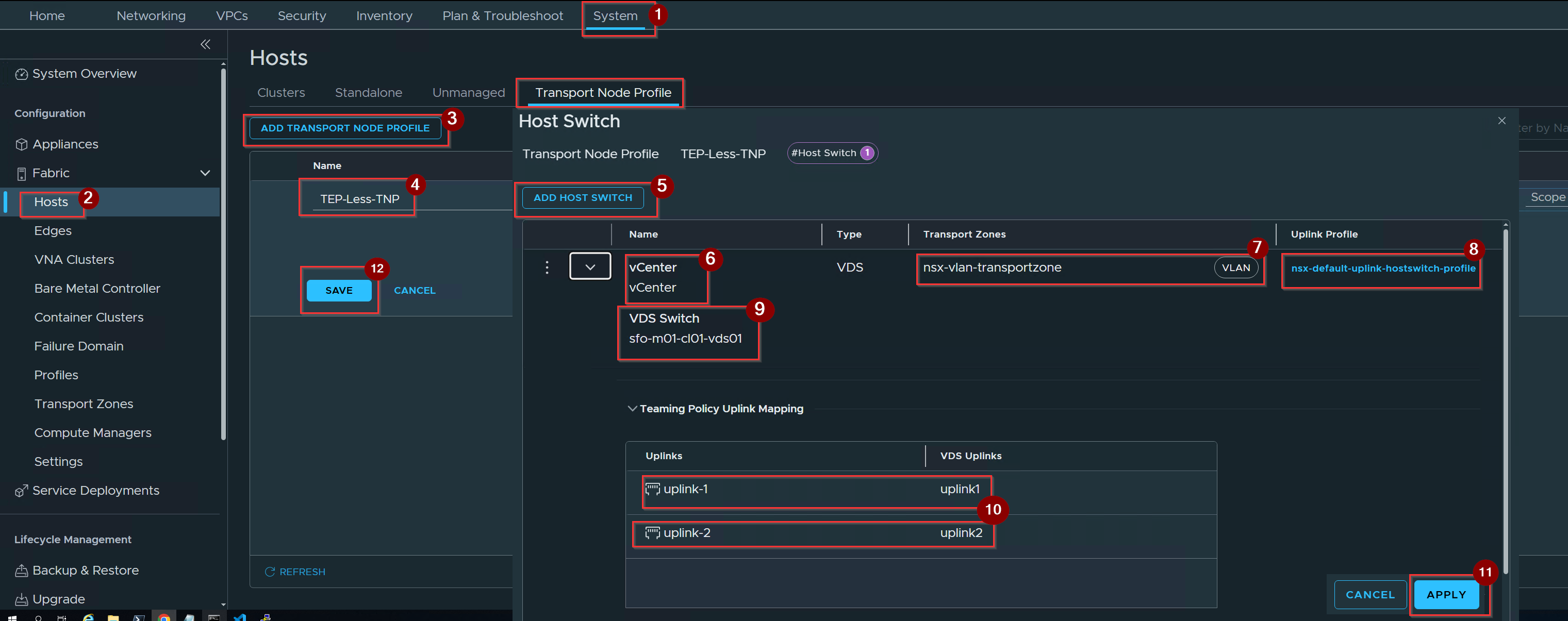
- Click on System.
- Click on hosts under fabric.
- Click on Add Transport Node Profile.
- Give the name of the profile.
- Click on Set under host switch and click on Add Host switch.
- Select the vCenter.
- Select the Transport Zone -Vlan.
- Select the Uplink Profile.
- Select the VDS.
- Select the teaming policy uplink profile.
- Click on Apply.
- Click on Save.
2. Prepare Cluster via Configure NSX (Advanced):
Capture 1:-
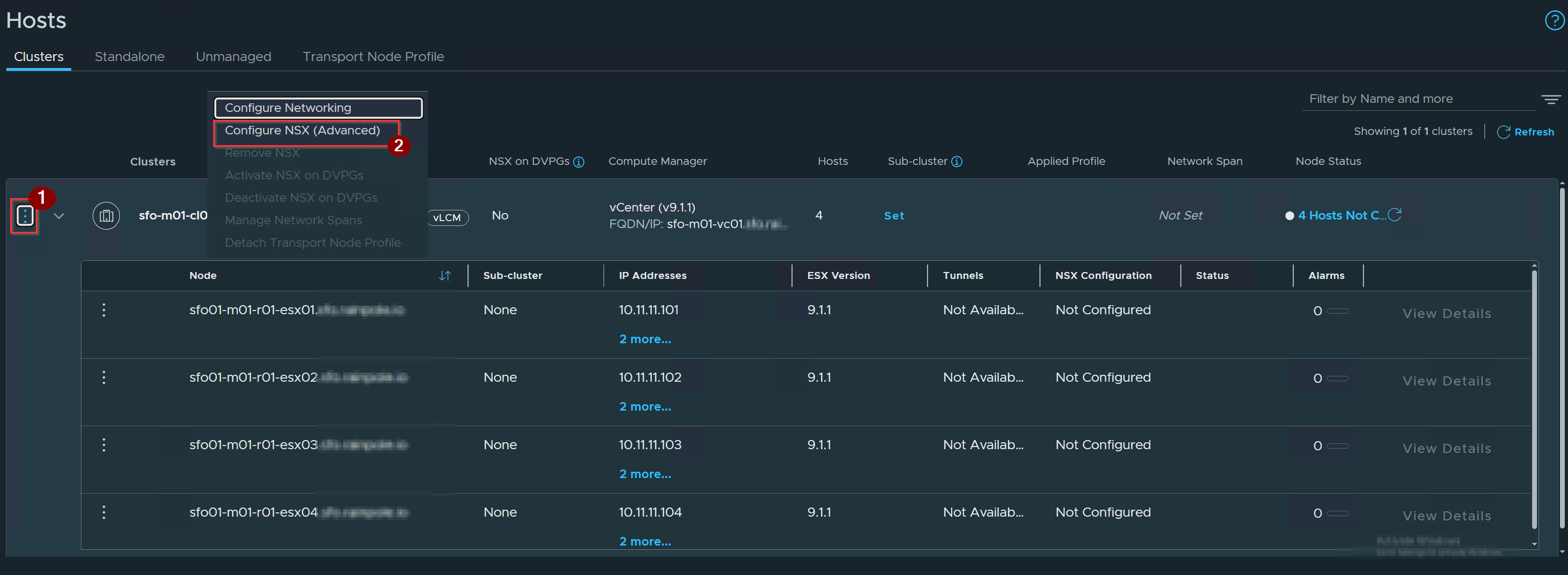
- Locate your target 4-host cluster, click its three-dot menu (…),
- Select Configure NSX (Advanced).
Capture 2: –
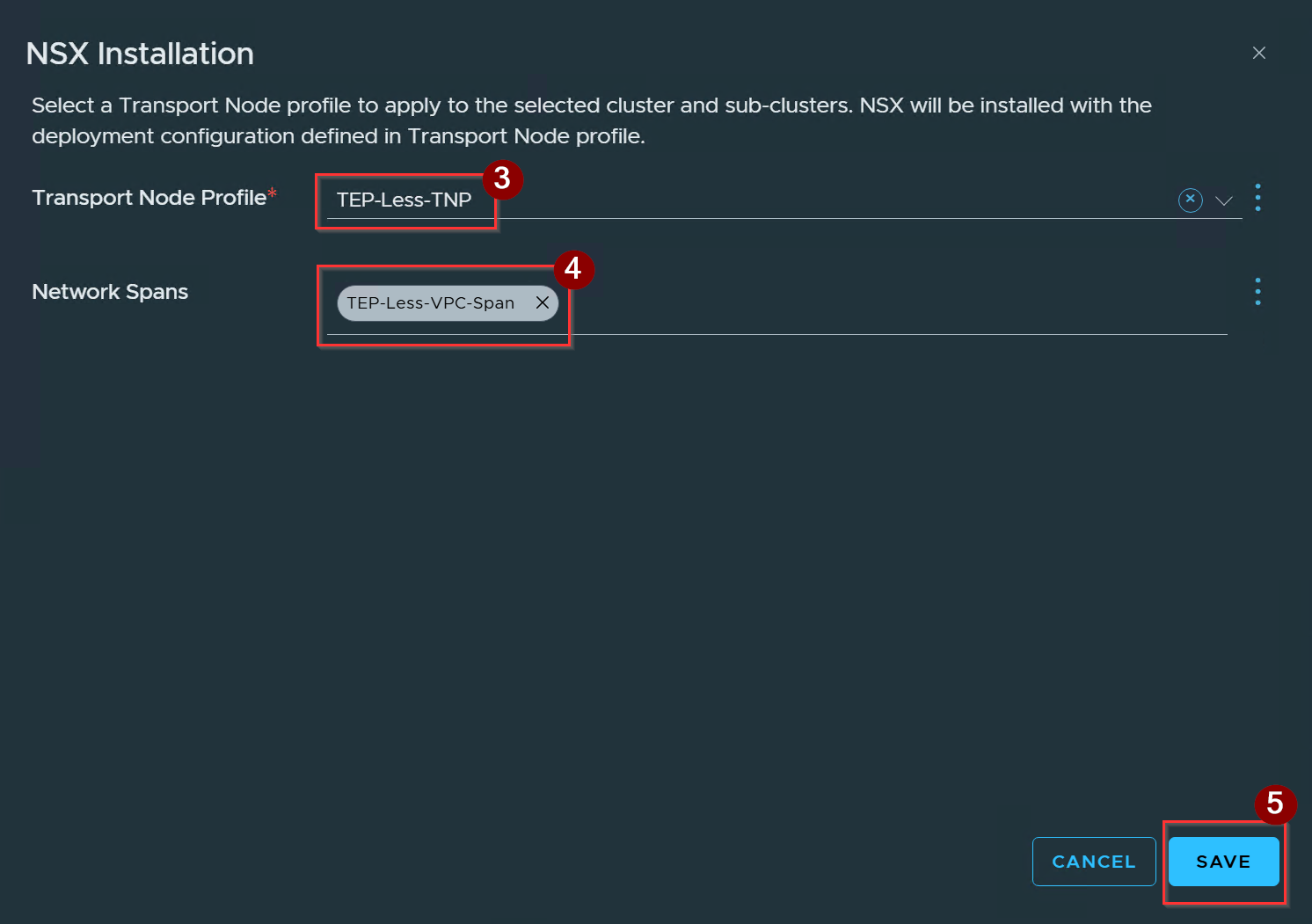
3. Select the transport Node.
4. Select the Network Spans.
5. Click on Save.
Capture 3:-
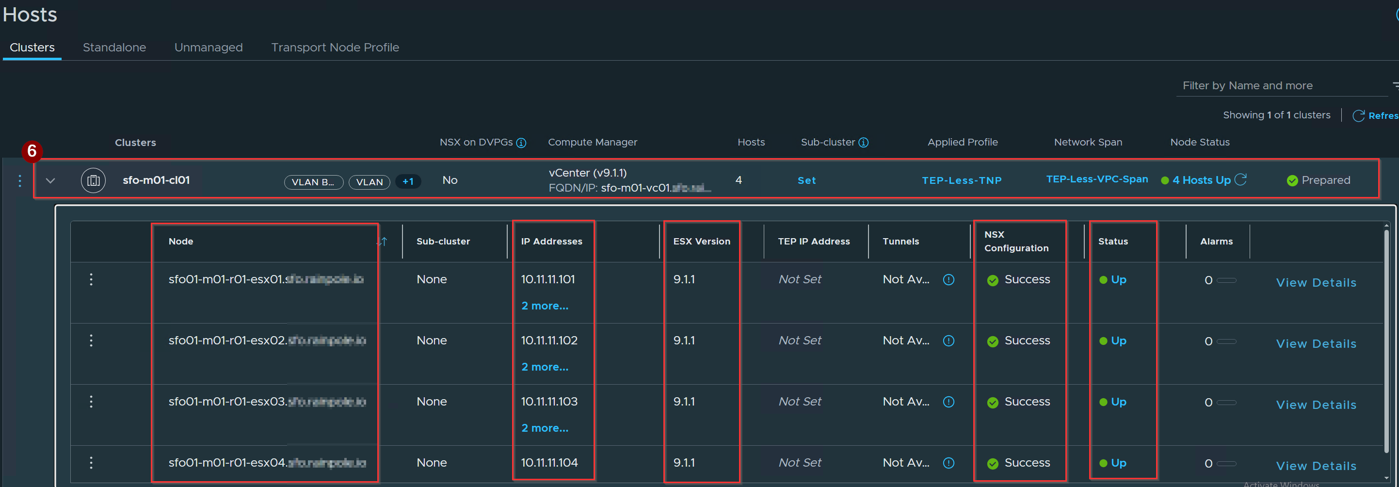
6. NSX prepares the host cluster in TEP-less mode and binds it directly to the Network Span.
Note: If your cluster uses vSphere Configuration Profiles, you can alternatively navigate to vSphere Client > Hosts and Clusters > Select Cluster > Configure > NSX > Configure Networking > Manage Network Spans to attach TEP-Less-VPC-Span
Step 3: Provision Transit Gateway (TGW) with TEP-Less Span
Capture 1: –
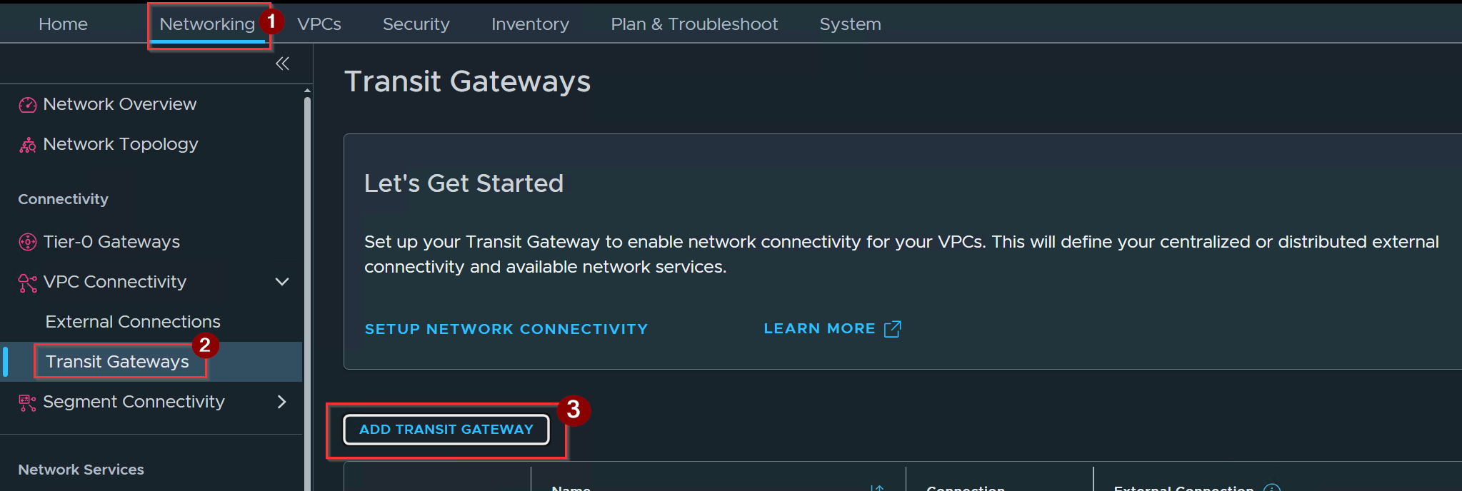
- Click on Networking.
- Click on Transit Gateways.
- Click on Add Transit Gateway.
Capture 2: –
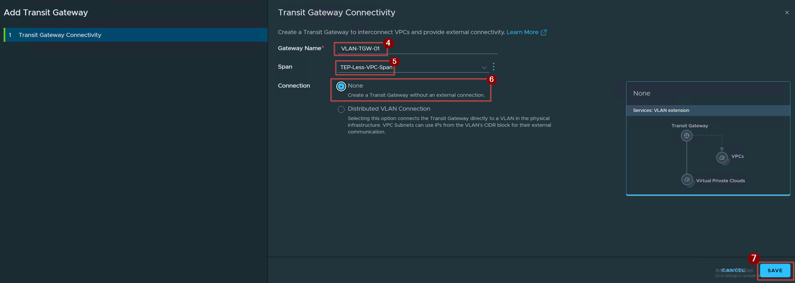
4. Give the name of the TGW.
5. Select the TEP-Less Span.
6. Connection select None.
7. Click on Save.
Comprehensive Comparison Matrix
| Comparison Vector | Connection: None | Distributed VLAN Connection |
| Layer 3 Gateway Location | Physical Network (ToR Switch SVI): Default gateway resides on physical network switches. | NSX Distributed Transit Gateway (DTGW): Default gateway and external boundary are managed by NSX. |
| North-South Routing Boundary | Offloaded to Underlay: NSX performs zero Layer 3 routing or egress path translation for external traffic. | Distributed Hypervisor Routing: ESXi hosts route traffic directly onto physical VLANs, bypassing Tier-0/Edge nodes. |
| Provider IPAM Requirement | Not Required: Subnets consume IP ranges directly assigned to physical VLAN SVIs. | Required: Must be backed by an External IPv4 Block provisioned in Provider IPAM. |
| Stateful Services (NAT, LB, FW) | Unsupported in NSX Layer: Stateful NAT, load balancing, and gateway firewalling are handled by physical firewalls/routers. | Supported via VNA Cluster: Integrates with Virtual Network Appliance (VNA) clusters to offload SNAT, DNAT, and Load Balancing without Edge nodes. |
| Data Path Encapsulation | Standard 802.1Q Tagging: Frames exit host physical uplinks (vmnic0/vmnic1) using native VLAN IDs (TEP-less). | Standard 802.1Q Tagging or EVPN-VXLAN: Frames exit directly over physical trunk VLANs or EVPN-VXLAN fabrics. |
| Inter-VPC (East-West) Routing | Supported strictly for internal VPC-to-VPC routing within the same project context. | Supported alongside direct North-South external reachability across projects. |
| Infrastructure Prerequisites | Network Span + Cluster VDS + Physical ToR SVI. | Network Span + External IPv4 Block + Distributed External Connection + Optional VNA Cluster. |
| Primary Use Cases | • TEP-less VLAN-backed VPCs • Air-gapped / Isolated sandbox environments • Enterprise workloads utilizing existing physical ToR gateways | • High-throughput AI/ML clusters needing NSX NAT • Edge-less VPC deployments requiring cloud-style IPAM • Distributed North-South routing with optional VNA stateful services |
Capture 3: –

As we can validate the TGW is successfully created.
Step 4: Provision VPC
Capture 1: –
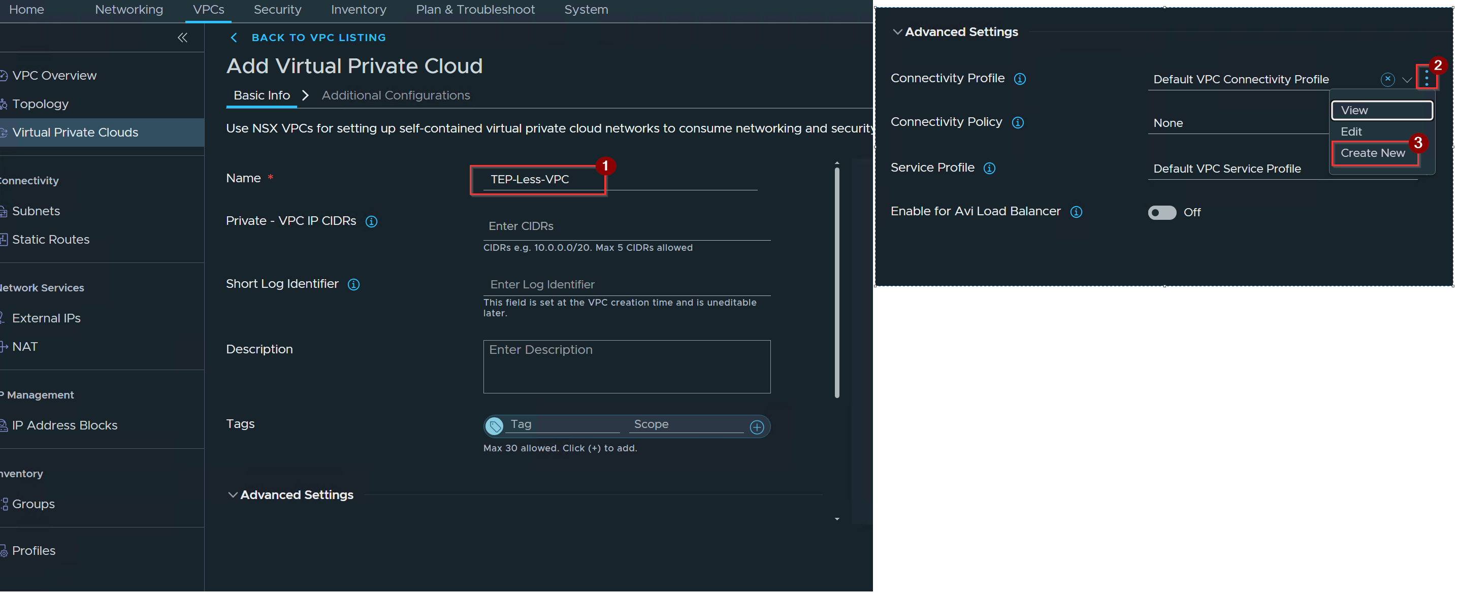
- Give the name of VPC.
- Under Advanced Settings–> Connectivity profile click on 3 dots.
- Click on Create New.
Capture 2: –
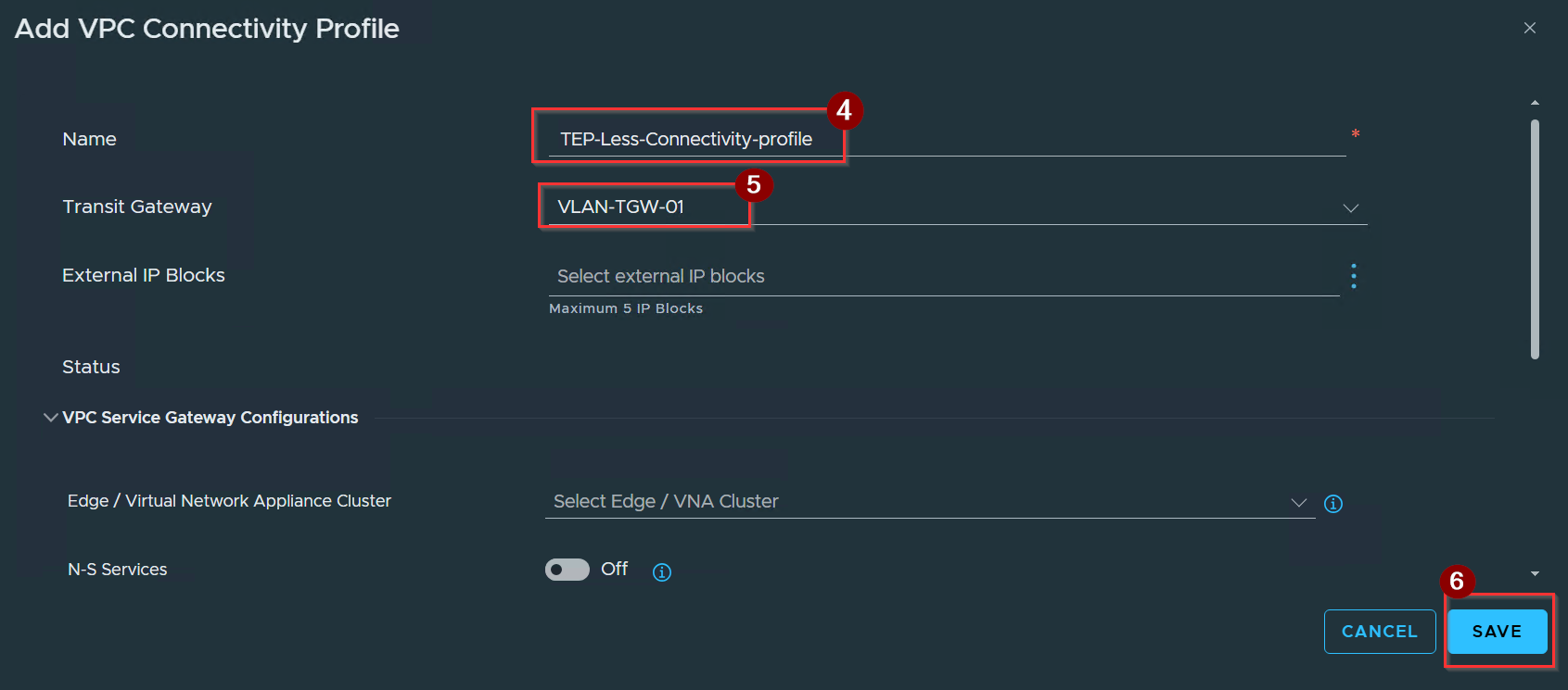
4. Give the name of the connectivity profile.
5. Select the transit gateway.
6. Click on Save.
Capture 3: –
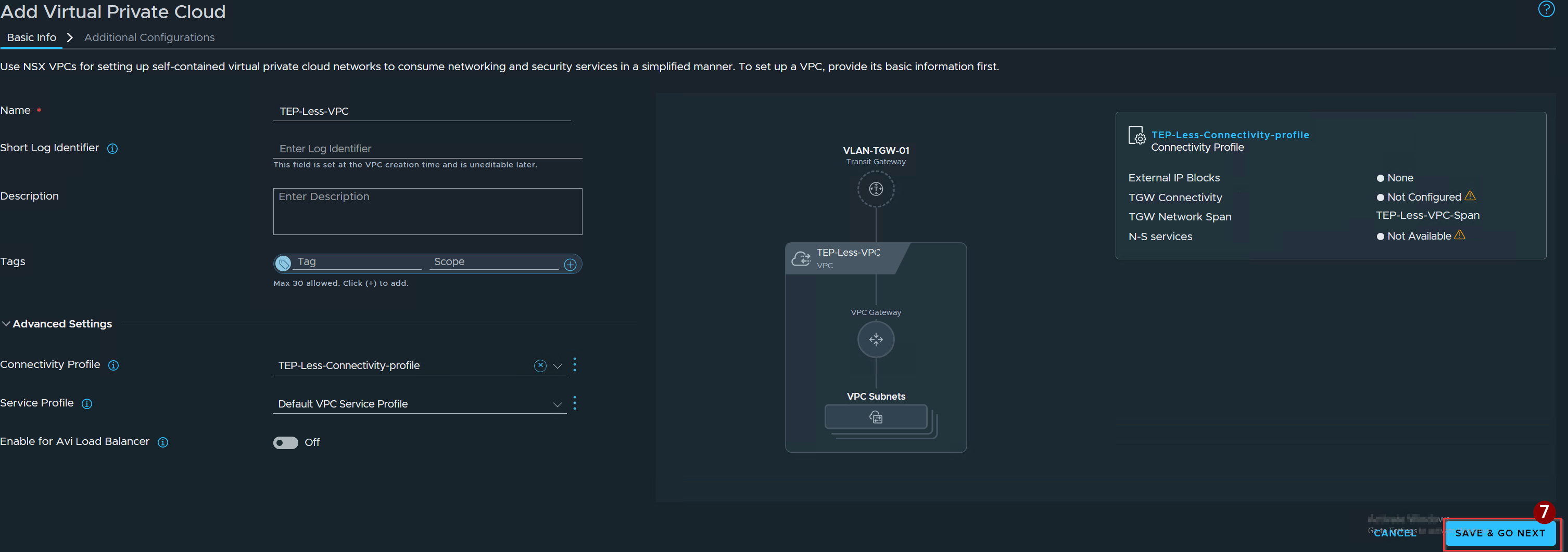
7. Click on Save & Go Next.
Capture 4: –
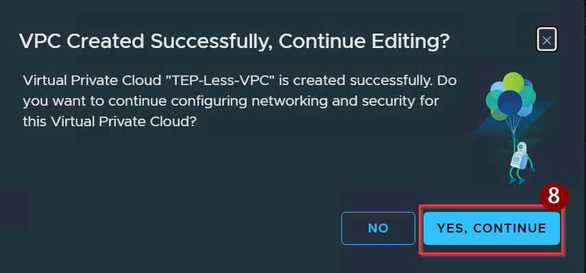
8. Click on Yes, Continue.
Capture 5:-
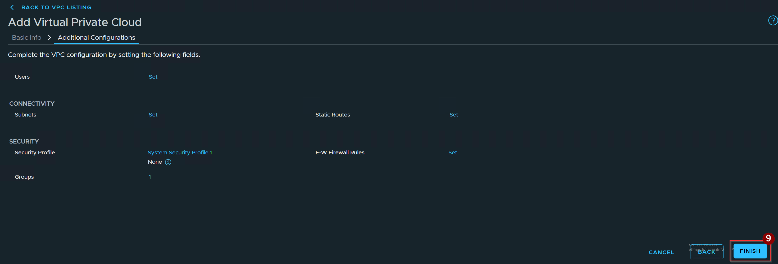
9. Click on Finish.
Capture 6: –

As we can validate VPC is successfully created.
Step 5: –Create a distributed VLAN external connection
Capture 1: –
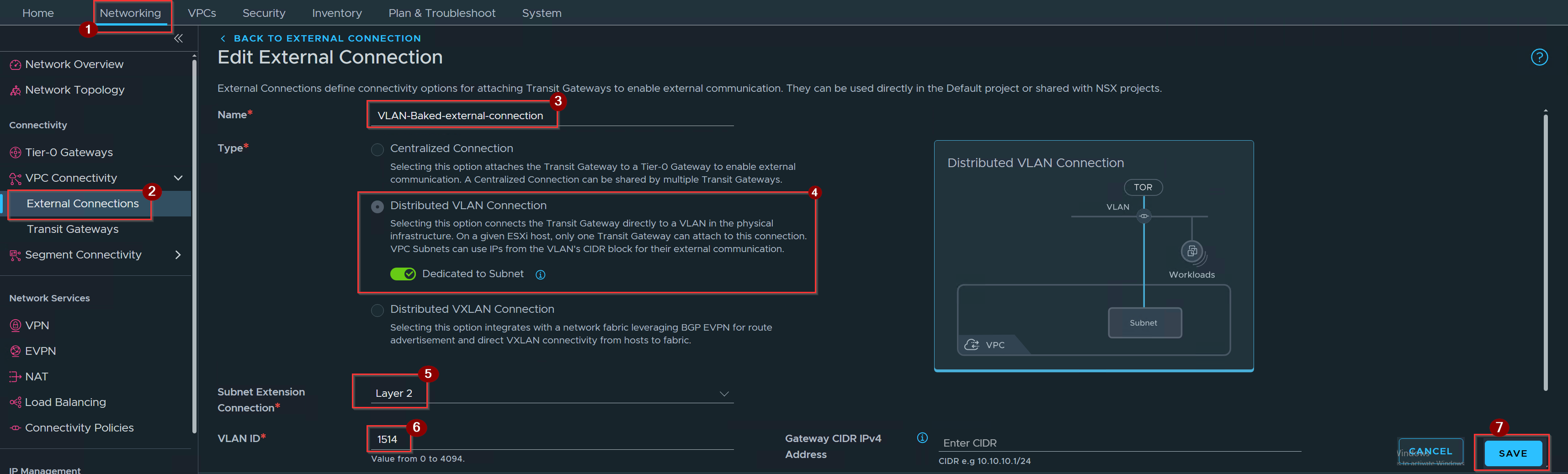
- Click on Networking.
- Click on external connections under VPC connectivity.
- Give the name of External Conenction.
- Click on Distributed Vlan connection radio button & Turn on the Dedicated to Subnet toggle.
- Set the Subnet Extension Connection to Layer 2.
- Give the Vlan id.
- Click on Save.
Capture 2: –

As we can validate the external connection is successfully created.
Step 6: –Add a subnet to the VPC
Capture 1: –
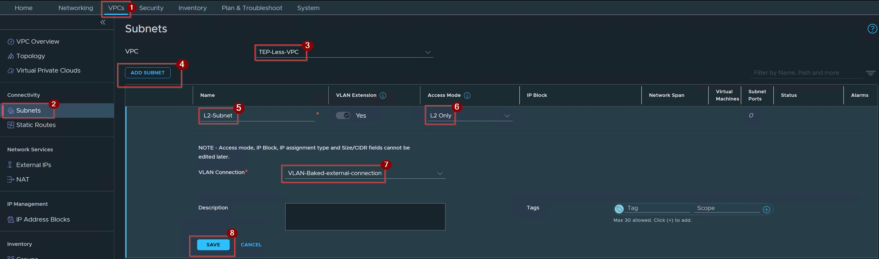
- Click on VPCs.
- Click on Subnets under connectivity.
- Select the VPC.
- Click on Add subnet.
- Give the name of the subnet.
- Select the Access mode.
- Select the vlan conenction.
- Click on Save.
Capture 2:-
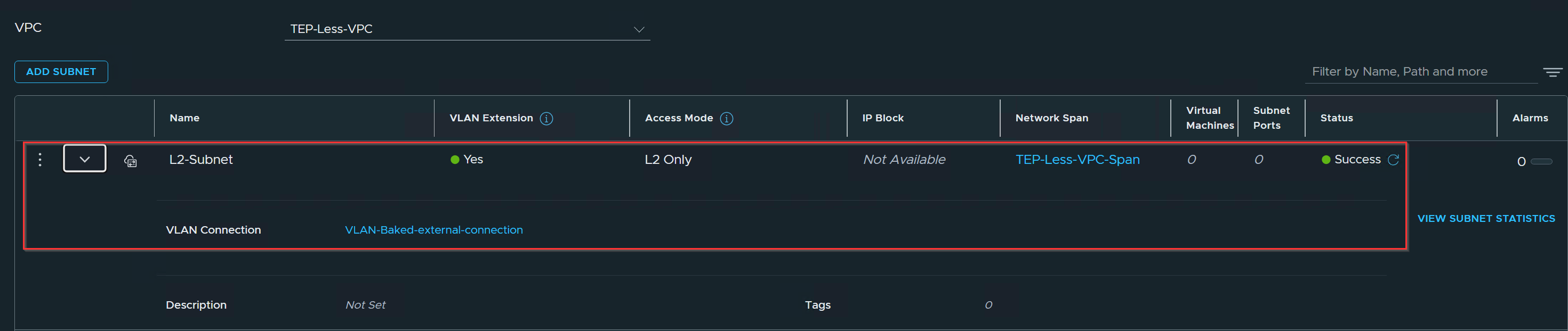
As we can validate the VPC l2 subnet is successfully created.
Step 7: –Attach VM Workloads and Verify Connectivity
Capture 1: –
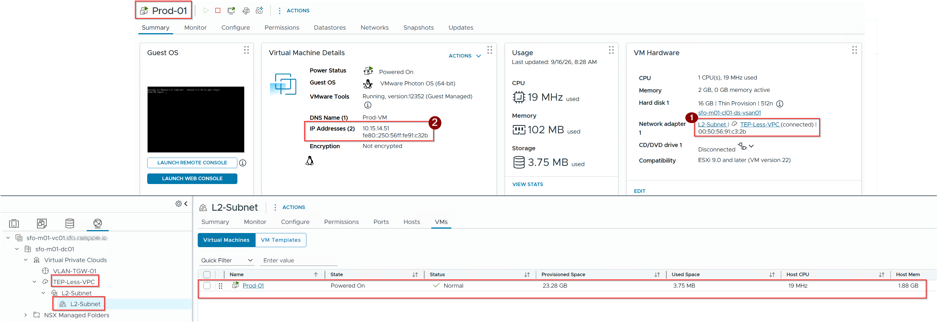
- Prod-01 Vm connected to TEP-Less-VPC l2 Subnet.
- Prod-01 VM getting IP from the Vlan 1514.
Capture 2: –
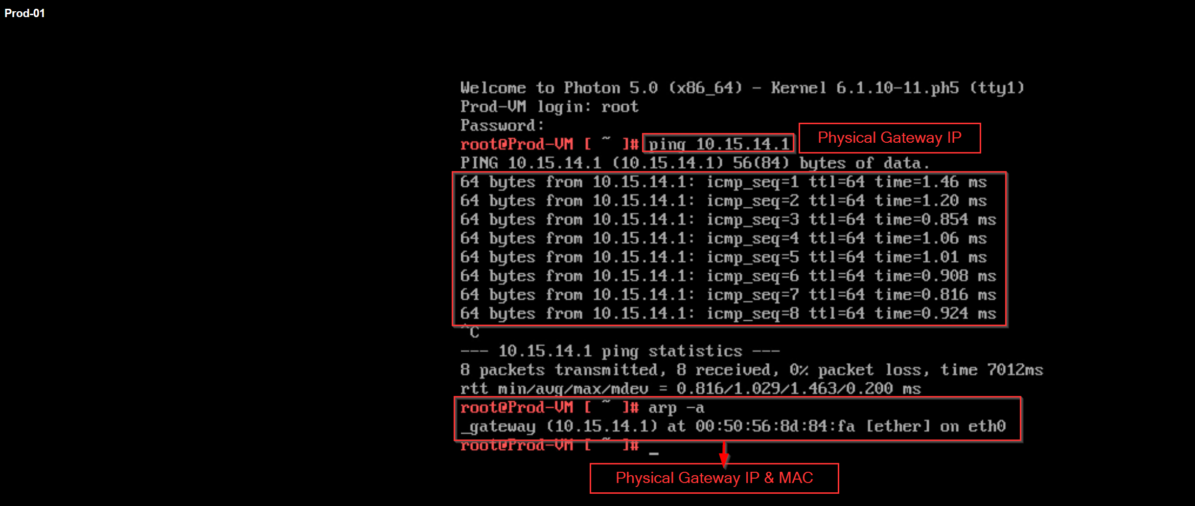
As we can see we are successfully reached to physical gateway from TEP-LESS-VPC-L2 Subnet.
Summary
VLAN-backed VPCs in TEP-less mode provide an efficient path to adopt VCF 9.1 Virtual Private Clouds without modifying physical network MTUs or managing host TEP IP infrastructures. By leveraging TEP-less Transport Node Profiles and binding host clusters to Network Spans, organizations can seamlessly blend traditional physical VLAN infrastructure with cloud-style self-service multi-tenancy.
 Puneet Sharma
Leave a comment