

- Introduction
- Architectural Dependencies Checklist
- The Default SNAT Verification Runbook
- The User-Defined SNAT Verification Runbook
- Egress Traffic Flow Packet Walk (Traceflow Mapping)
- Asymmetric Routing and Connection State Failures
- Conclusion
Introduction
VMware Cloud Foundation (VCF) 9.1 decouples stateless distributed routing (DR context in hypervisor kernel space) from stateful edge services via the Virtual Network Appliance (VNA) framework. Egress traffic requiring Source Network Address Translation (SNAT) is intercepted by the host kernel and tunneled via Geneve/TEP to a designated Tier-1 Service Router (SR) namespace inside the VNA appliance cluster. This post isolates the underlying data-plane mechanics, CLI validation runbooks, and active Traceflow paths for both Default Auto SNAT and User-Defined SNAT.
VNA Stateful Services Series
- Part 1: Beyond get nat: Inside the VCF 9.1 VNA Architecture and Stateful NAT Data Plane
https://puneetsharma.blog/2026/07/20/beyond-get-nat-inside-the-vcf-9-1-vna-architecture-and-stateful-nat-data-plane/ - Part 2: Inbound Publishing: Architecting Default and User-Defined DNAT Pipelines
https://puneetsharma.blog/2026/08/05/inbound-publishing-architecting-default-and-user-defined-dnat-pipelines-in-vcf-9-1-vna/ - Part 3: The VNA Bypass: Mechanics of Lateral Inter-VPC East-West Routing (Upcoming)
- Part 4: Elastic IP (EIP) Traffic vs. SVM Redirection Bypass Mechanics (Upcoming)
- Part 5: Demystifying the VNA DNS Forwarder Under the Hood (Upcoming)
- Part 6: Scaling Applications with the VNA L4/L7 Load Balancer (Upcoming)
Architectural Dependencies Checklist
Before stateful NAT features can be provisioned or inspected via the CLI, the underlying fabric must fulfill these exact infrastructure requirements:
| Architectural Component | Configuration Requirement | Technical Validation Target |
| VNA Cluster Health | Deploy a minimum of two VNA appliance nodes (via vCenter or NSX Manager Fabric) ensuring the operational status returns a green Success state. | Validates active/standby state mirroring availability for the tenant Tier-1 Service Router (SR) context. |
| External IP Address Blocks | Pre-create a dedicated IP address block within NSX with its visibility scope explicitly toggled to External. | Allocates the valid translation pool; internal tenant overlay blocks are rejected by the NAT engine schema. |
| Distributed Transit Gateway (D-TGW) | Initialize a custom Transit Gateway utilizing the Distributed VLAN Connection profile type. | Connects the External IP block directly to the multi-tenant VPC fabric overlay boundaries. |
| Upstream Path Symmetry | Configure upstream physical network layers (BGP parameters or static routing tables on Top-of-Rack core switches) to point the External IP Block CIDR to the VNA endpoints. | Guarantees deterministic, symmetric return paths to prevent connection tracking drops inside the VNA firewall state table. |
Supported NAT Capabilities Matrix in VCF 9.1 VNA
The Virtual Network Appliance (VNA) framework in VCF 9.1 natively supports the following translation mechanisms within the tenant data plane:
| NAT Mechanism | Configuration Type | Data-Plane Functional Mechanics & Use Case |
| Auto SNAT | Automated (VPC Boundary) | Automatically maps outbound tenant overlay subnets to a dynamically allocated External IP pool block to provide default internet/egress connectivity. |
| User-Defined NAT (Custom Rules) | Manual (Policy-driven) | Provides granular configuration control over Source NAT (South-to-North egress) and Destination NAT (North-to-South ingress) mappings based on explicit IP, port, or protocol match criteria. |
| Elastic IP(EIP) | Object-driven (1:1 Binding) | Establishes a direct 1:1 static address allocation mapped to an individual workload interface (vNIC). It leverages kernel-accelerated Fastpath data paths to optimize throughput and lower latency. |
| No-SNAT (NAT Bypass) | Manual (Exemption Rule) | Creates explicit policy exemptions within the translation ruleset to deliberately preserve original internal IP headers across specified network boundaries or shared infrastructure segments. |
Note: VCF 9.1 VNA explicitly omits Reflexive NAT because it is a stateless mechanism that bypasses the core gateway firewall connection tracking table (get firewall connection state), which breaks the stateful flow auditing and inline security inspection required by the VNA architecture.
Deep Dive: Default Auto SNAT vs. User-Defined SNAT
The VNA subsystem processes outbound source translation through two distinct methodologies depending on the level of topology granularity and policy control required by the network architecture:
| Architectural Attribute | Default Auto SNAT | User-Defined SNAT |
| Data-Plane Engine | Systemic, control-plane generated catch-all rule mapping internal overlay subnets to the External IP block. | Policy-driven execution matching explicit Layer-3/Layer-4 criteria prior to header manipulation. |
| Matching Granularity | Broad environment-wide context (all internal tenant overlay CIDRs bound to the VPC interface). | Fine-grained matching matrices (granular source/destination IP pairs, CIDR subnets, ports, and protocols). |
| Operational Intent | Standardized, bulk egress internet/WAN transit without specific internal host isolation requirements. | Regulatory compliance auditing, multi-tenant whitelisting, and strict production/non-production zone segregation. |
| Provisioning Mode | Automated orchestration via a binary toggle switch inside the VPC or D-TGW layout wizard. | Manual ruleset injection via the tenant VPC NAT Rules configuration array (Action: SNAT). |
The Default SNAT Verification Runbook
Because VCF 9.1 compiles SNAT mappings directly into the stateful gateway firewall path instead of traditional layer-3 routing tables, running legacy routing commands will return an empty output. Use this step-by-step runbook from the active VNA node terminal to query, isolate, and verify active outbound operations.
Discover the Infrastructure Validation
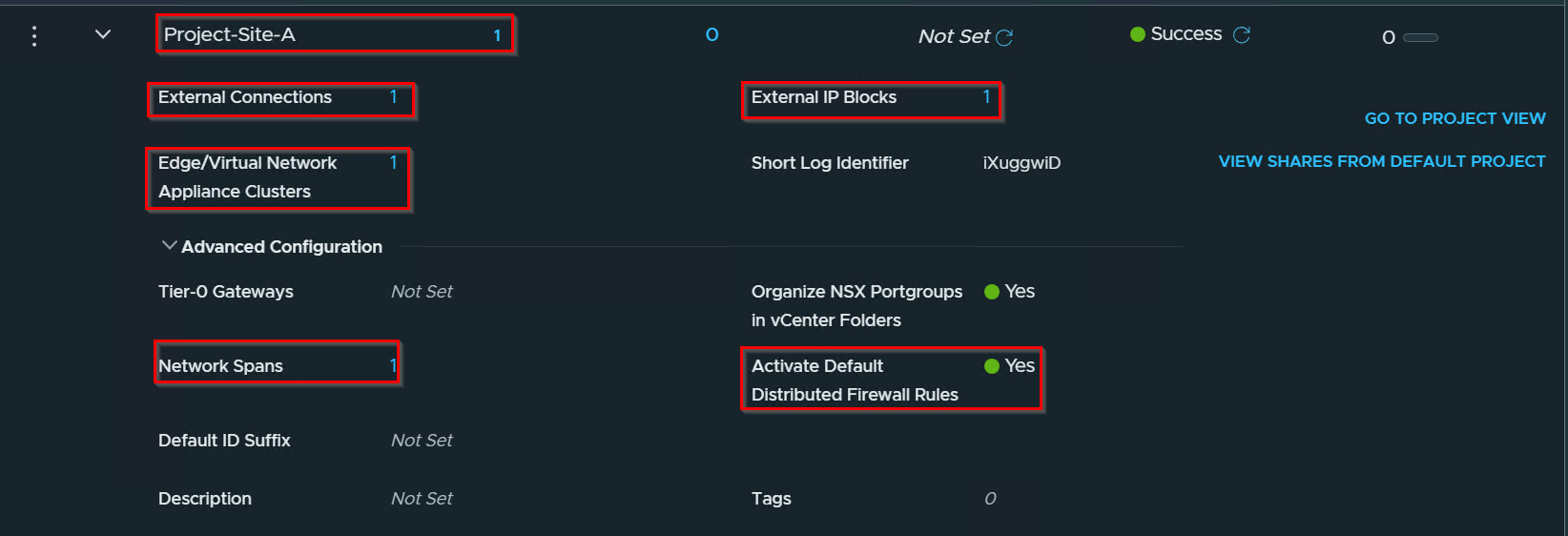
Capture 1:-
Project Validation
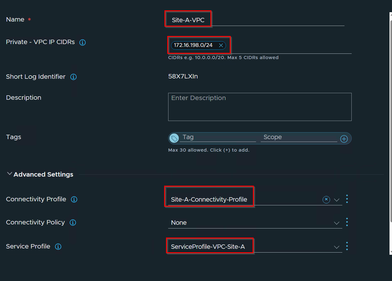
Capture 2:-
VPC Validation
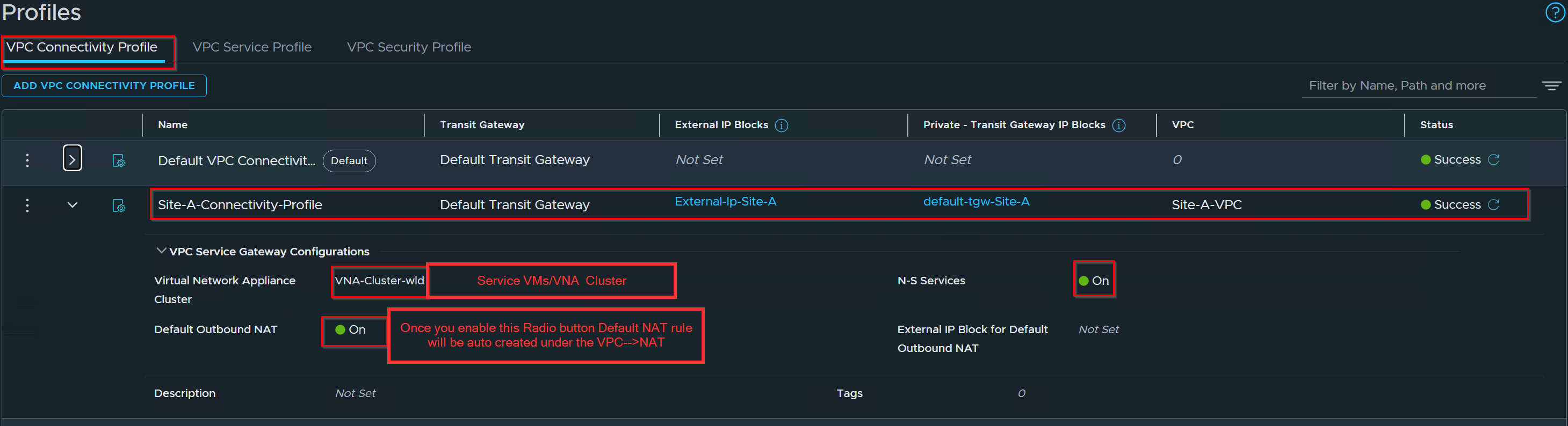
Capture 3: –
Connectivity Profile Validation
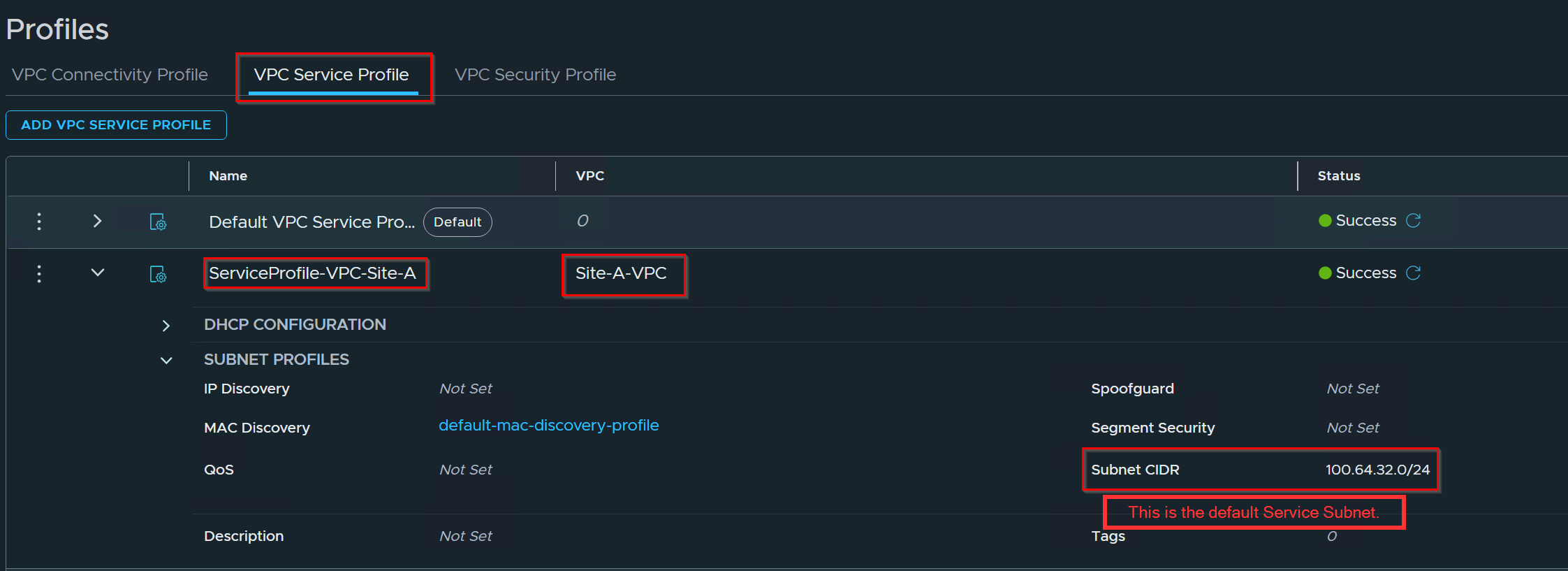
Capture 4: –
VPC Service Profile validation
Capture 5: –
Default NAT Rule Validation
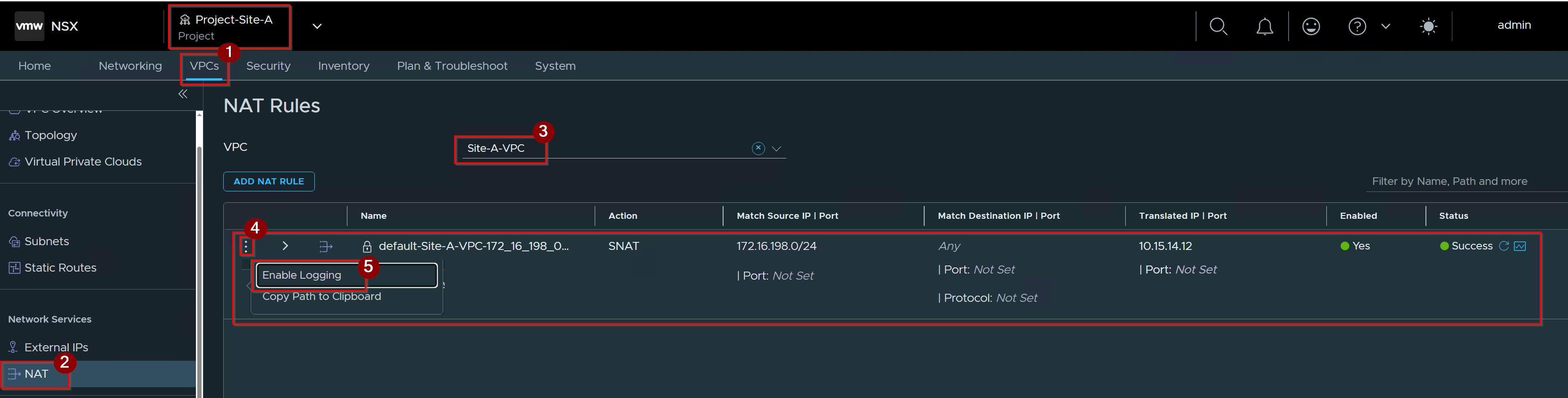
- Click on VPC Under Project.
- Click on NAT under network services.
- Select the VPC.
Note:- As we can see, the default SNAT rule is automatically created with the matched source IP set to the private subnet and the translated IP set to the external IP block. - Click on 3 dots.
- Click on enable logging.
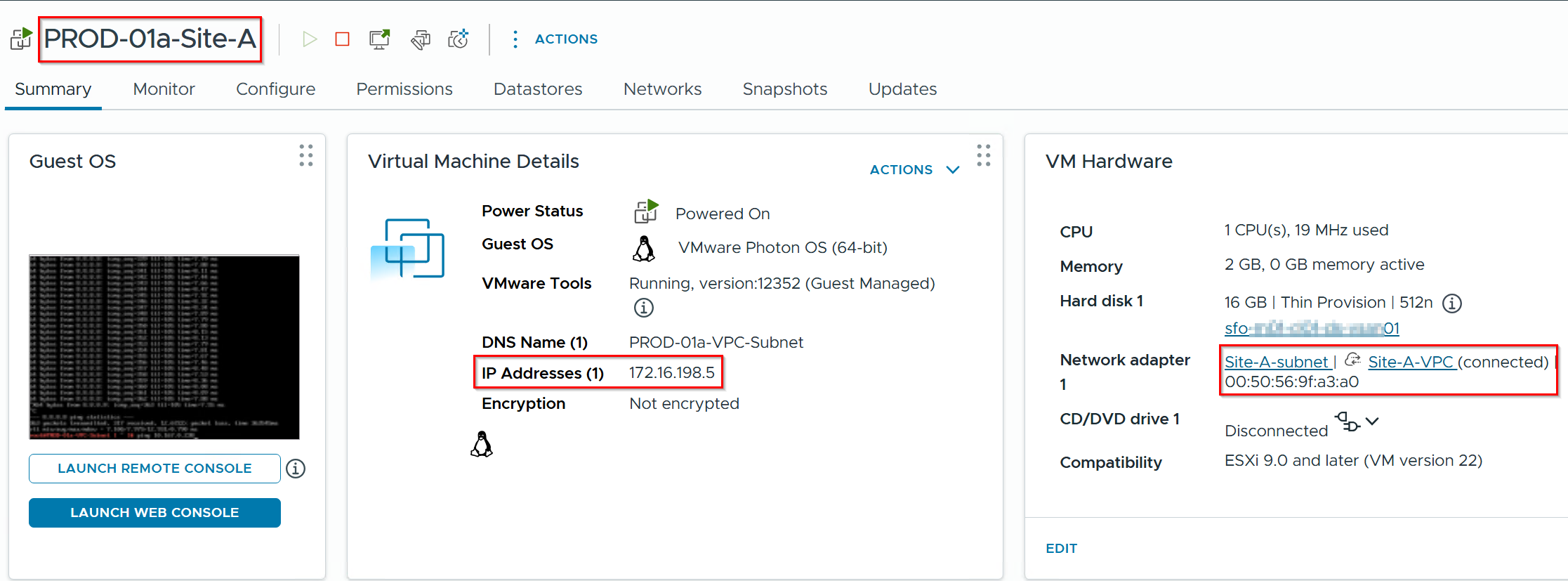
Capture 6:-
Source VM -172.16.198.5 Validation.
Discover the Gateway UUID and Network Namespaces
Capture 1: –
Establish an SSH session to the active VNA appliance node

cmd: – get vpcs
Note:- note down the VRF ID.
Capture 2: –
Extract the Logical Interface (LIF) Identifiers
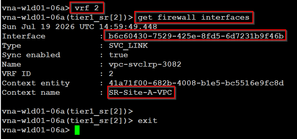
cmd: – get firewall interfaces (run this command under VPC VRF)
All rules will be applicable on interface b6c60430-7529-425e-8fd5-6d7231b9f46b.Because stateful NAT policies are bound to specific physical and overlay boundaries rather than the global router object, you must target the specific interface processing the traffic:
Capture 3: –
Inspect the Programmed Firewall and NAT Ruleset
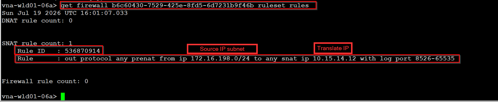
cmd :- get firewall UUID ruleset rules.
the active ruleset array, allowing you to confirm that the systemic Auto SNAT rule (Internal Overlay -> External Pool IP) entries are successfully compiled and loaded on the interface data path.
Capture 4: –
Validate Real-Time packet Capturing
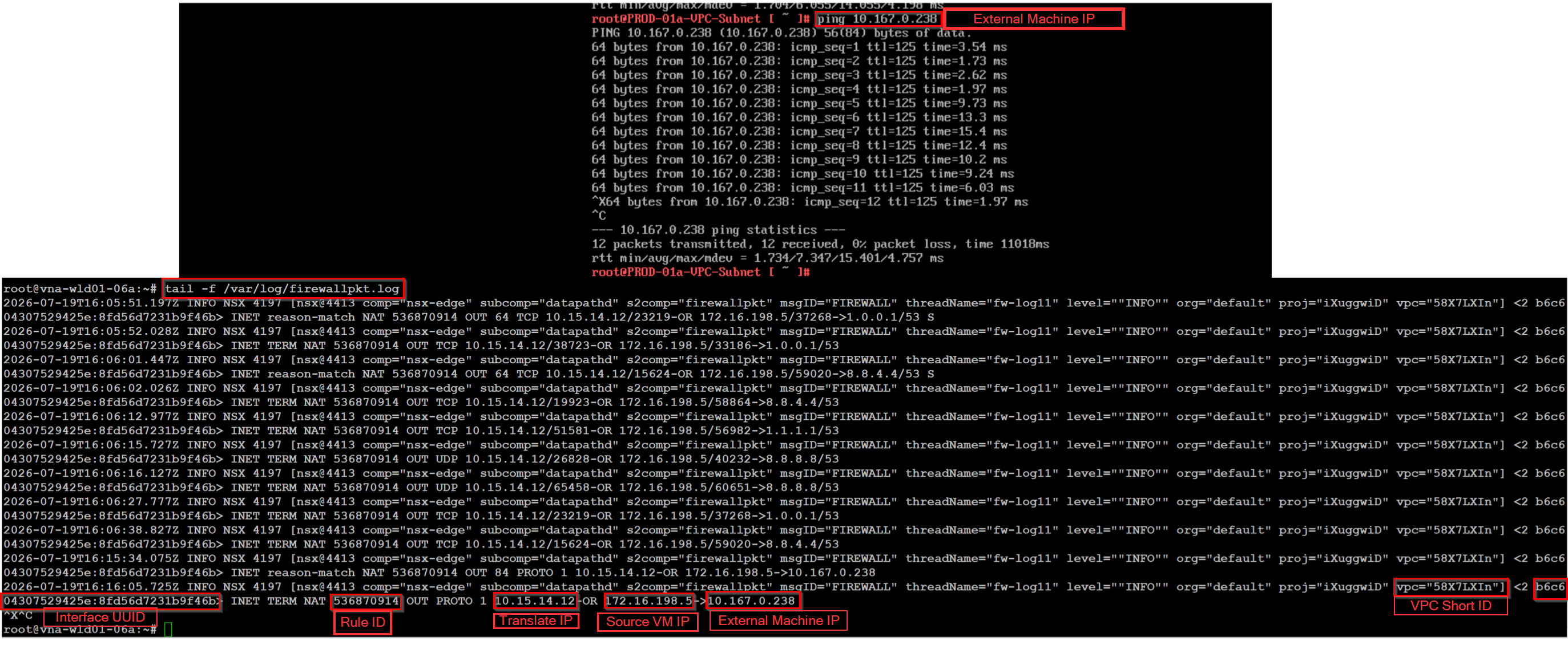
cmd: – tail -f /var/log/firewallpkt.log
(run this cmd with root creds ).
Outbound SNAT Verification: The log tracks an active outbound session where the internal source VM (172.16.198.5) is statefully masked and tracked behind the public outbound IP (10.15.14.12) to reached external VM IP (10.167.0.238).
The User-Defined SNAT Verification Runbook
Capture 1: –
Remove the default SNAT rule if you have.
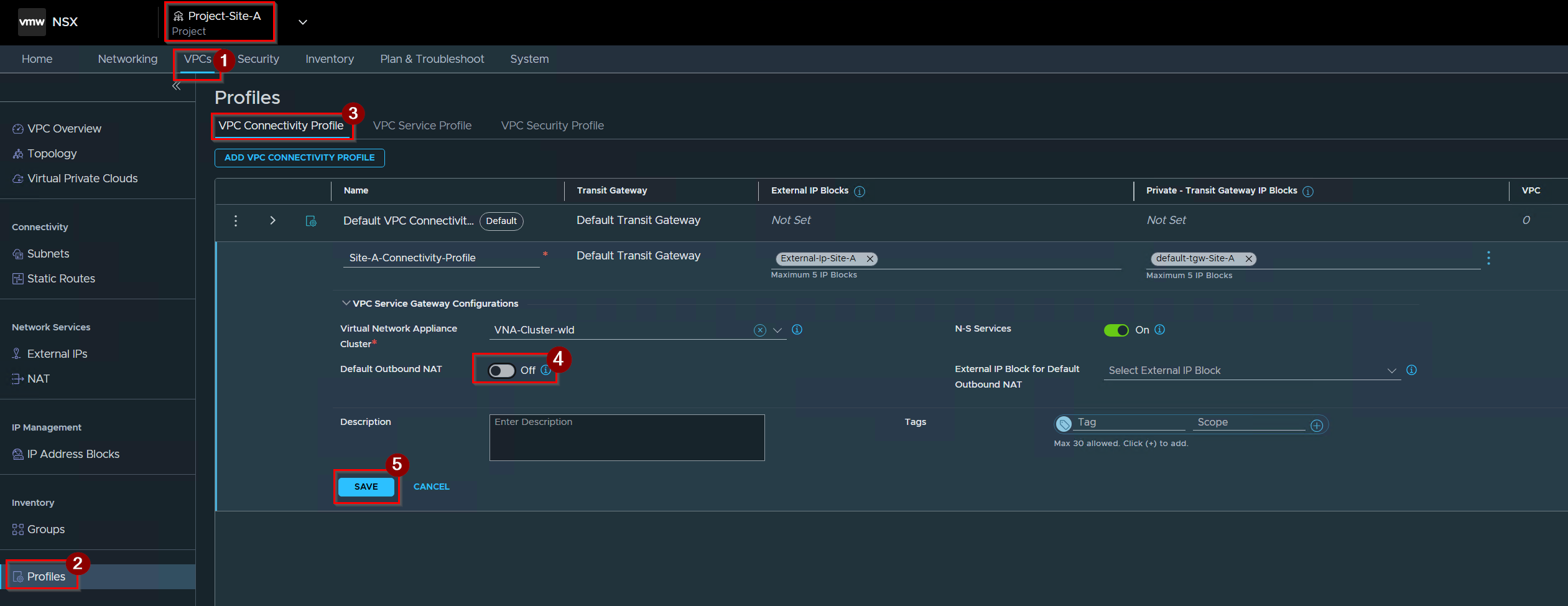
1.Click on VPCs under Project.
2. click on Profiles.
3. Click on VPC Connectivity Profile.
4. Off the radio button after the Default outbound NAT.
5. Click on Save.
Capture 2: –
User-Defined NAT rule Creation
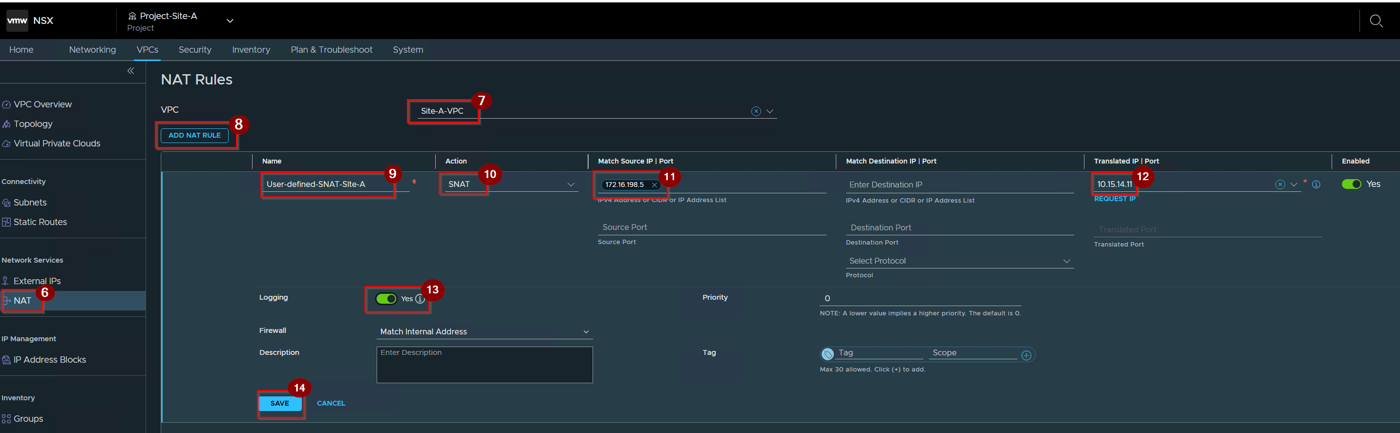
6. Click on NAT under VPC.
7. Select the VPC.
8. Click on ADD NAT RULE.
9. Give the Name.
10. Select the Action.
11. Give the Source IP port.
12. Give the Translate IP.
13. Enable the logging.
14. Click on Save.
Capture 3: –
Validate Real-Time packet Capturing
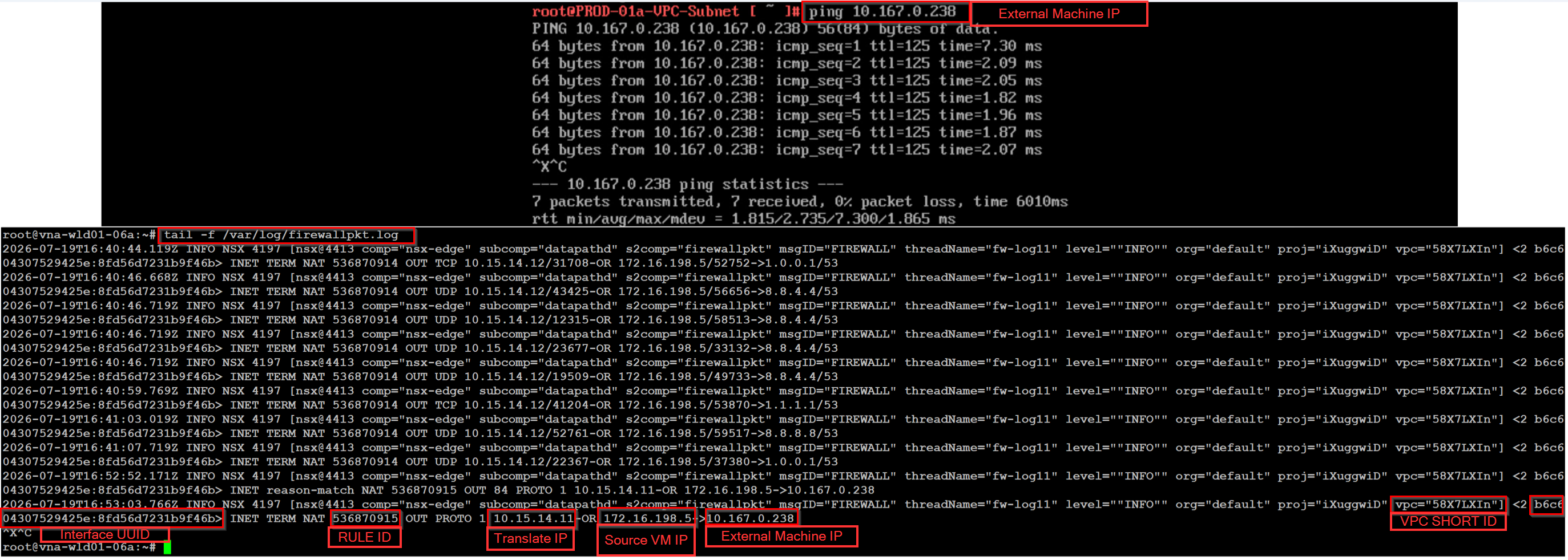
cmd: – tail -f /var/log/firewallpkt.log
(run this cmd with root creds ).
Outbound SNAT Verification: The log tracks Rule ID (536870915) an active outbound session where the internal source VM (172.16.198.5) is statefully masked and tracked behind the public outbound IP (10.15.14.11) to reached external VM IP (10.167.0.238).
Egress Traffic Flow Packet Walk (Traceflow Mapping)
Now that we have the diagnostic tools to dump the state tables and rulesets, we can track a live outbound unicast ICMP packet (Source: 172.16.198.5 -> Destination: 10.167.0.238) as it traverses the multi-tenant VNA cluster and hypervisor fabric based on verified Traceflow path metrics.
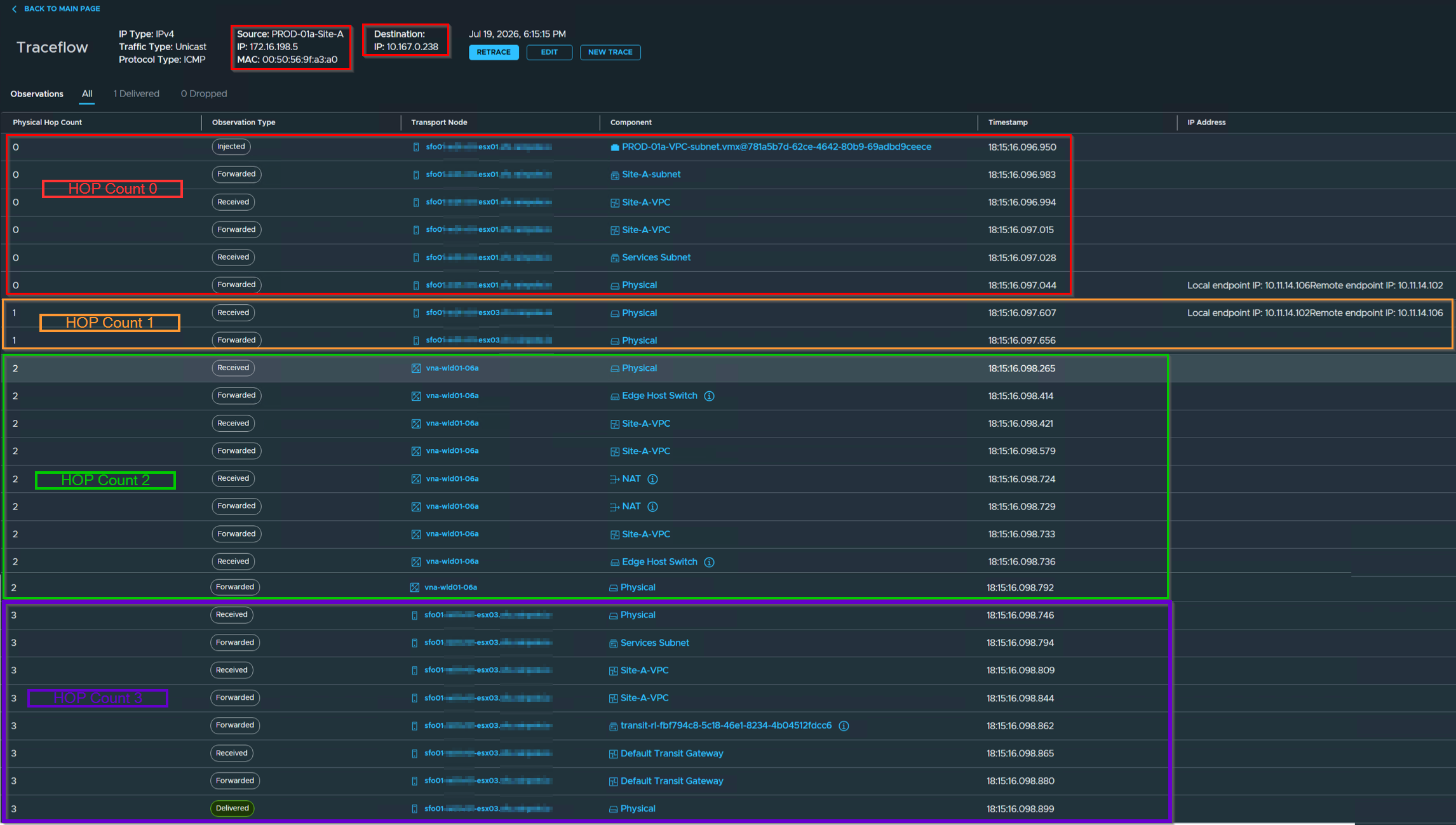
Step-by-Step Chronological Packet Walk
HOP Count 0: Compute Node Origin (sfo01-xx1-xx1-esx01)
- [Injected]: The virtual machine workload
PROD-01a-VPC-subnet.vmxinitiates the raw ICMP frame into the vSwitch port. - [Forwarded]: The frame passes through the logical layer-2 segment
Site-A-subnet. - [Received]: The local hypervisor kernel intercepts the frame at the ingress boundary of the
Site-A-VPCDistributed Router (DR) context. - [Forwarded]: The DR routing table resolves the next hop, identifying a destination path requiring stateful perimeter services.
- [Received]: The frame transitions into the
Services Subnetinterface context for edge encapsulation. - [Forwarded]: The ESXi host maps the packet to the Geneve underlay transport engine, encapsulating the payload and transmitting it from the Local Tunnel Endpoint (TEP:
10.11.14.106) toward the VNA target (Remote TEP:10.11.14.102).
HOP Count 1: Core Fabric Transit Node (sfo01-xx1-xx1-esx03)
- [Received]: The underlay transport node intercepts the encapsulated Geneve outer header at the physical layer (Local:
10.11.14.102| Remote:10.11.14.106). - [Forwarded]: The fabric transit node executes an internal layer-3 underlay lookup and switches the tunnel frame directly to the edge deployment host boundary.
HOP Count 2: Stateful VNA Appliance Layer (vna-wld01-06a)
- [Received]: The active service appliance node ingests the Geneve payload at its physical network interface boundary.
- [Forwarded]: The packet is decapsulated and steered through the hardware-coupled
Edge Host Switchinfrastructure. - [Received]: The unencapsulated inner ICMP packet hits the ingress loop of the centralized
Site-A-VPCService Router (SR) instance. - [Forwarded]: Traffic is statefully directed into the interface-bound gateway policy ruleset matrix.
- [Received]: The frame enters the stateful
NATtranslation processing engine. - [Forwarded]: The
NATengine registers a new flow entry inside the connection tracking table, overwrites the private source address (172.16.198.5) with the assigned public IP pool header, and calculates the new IP header checksum. - [Forwarded]: The translated packet is routed out of the
Site-A-VPCService Router namespace boundary. - [Forwarded]: The modified packet loops back through the internal
Edge Host Switchring for external encapsulation. - [Forwarded]: The VNA node encapsulates the frame and transmits it back onto the physical fabric transit network.
HOP Count 3: Egress Gateway Subsystem (sfo01-xx1-xx1-esx03)
- [Received]: The egress transport host receives the post-NAT frame from the physical fabric interface link.
- [Forwarded]: The packet is processed through the tenant
Services Subnetinterface block. - [Received]: The frame enters the external transit routing loop of the
Site-A-VPCcontext. - [Forwarded]: The router passes the frame downstream into the dedicated multi-tenant interconnect fabric segment.
- [Forwarded]: The flow matches the explicit transit path profile
transit-rt-fbf794c8-5c18-46a1-8234-4b04512fdcc6. - [Received]: The packet is accepted by the
Default Transit Gatewaylogical uplink context. - [Forwarded]: The gateway executes the final routing lookup targeting the next-hop upstream external router.
- [Delivered]: The statefully translated packet is pushed out of the physical infrastructure uplink and successfully handed off to the Top-of-Rack (ToR) switch fabric.
Asymmetric Routing and Connection State Failures
- Path Symmetry Requirement: Stateful VNA NAT requires strict traffic symmetry across the appliance cluster to ensure return traffic hits the original session-tracking node.
- Upstream Routing Failure: Upstream asymmetric routing causes return packets to land on an alternate VNA node that lacks the initial handshake record.
- Stateful Drop Engine: Lacking the matching entry in its local connection tracking table, the alternate node flags the flow as invalid and immediately drops the packets.
Conclusion
Breaking down outbound connectivity into automated bulk egress (Auto SNAT) or granular, custom policy pathways (User-Defined SNAT) ensures deterministic traffic management across multi-tenant VCF environments. By tracing the packet walk, we can see that understanding the VNA data plane requires shifting away from basic routing table lookups and focusing heavily on hypervisor-to-appliance encapsulation paths.
In our next installment, Part 2: Inbound Publishing: Architecting Default and User-Defined DNAT Pipelines, we will look at the opposite traffic direction and explore how to safely expose internal tenant resources to external core fabrics using destination translation rules.


Leave a Reply