

- Introduction
- Architectural Shift: VCF 9.0 vs. VCF 9.1
- The Four Connectivity Postures
- Data Plane Mechanics: Line-Rate Efficiency and Scaling Boundaries
- Verifying Connectivity Control in vCenter
- Conclusion
Introduction
In multi-tenant private clouds, governing communication between distinct Virtual Private Clouds (VPCs) assigned to the same project has historically been a security operations constraint. By default, networks within a project tenancy share a common routing domain via the Distributed Transit Gateway (DTGW). To prevent a development VPC from communicating with a production VPC, administrators were forced to apply stateful Layer 4 firewall policies.
While effective, using firewalls for basic network segmentation incurs an operational penalty. It bloats the Distributed Firewall (DFW) rule tables, consumes hypervisor CPU cycles for state tracking, and creates tight dependencies on security licensing.
VMware Cloud Foundation (VCF) 9.1 natively addresses this with VPC Connectivity Control. This capability shifts cross-VPC traffic boundaries off the firewall and pushes them directly down into the native logical routing fabric. Configurable directly from the VMware vCenter UI, this framework introduces specific policy types—Community, Isolated, and Promiscuous—to dictate routing boundaries natively without writing a single firewall rule, keeping the security plane lean and reserved for advanced threat inspection tasks.
Architectural Shift: VCF 9.0 vs. VCF 9.1
The addition of policy-based connectivity alters how tenant routing domains behave out of the box.
| Technical Attribute | VCF 9.0 VPC Routing | VCF 9.1 VPC Connectivity Control |
| Default Cross-VPC Behavior | Open Routing Interconnect: All VPCs connected to the same project-level gateway can route to one another by default. | Policy-Governed Interconnect: Cross-VPC routing boundaries are natively dictated by network-layer policy definitions. |
| Isolation Mechanism | Requires VMware vDefend Distributed Firewall or Edge Gateway ACLs to block inter-VPC leakage. | Native Routing Restrictions: Handled entirely at the network layer via automated route-filtering and lookup constraints. |
| Management Interface | Mandated switching between vCenter for compute and NSX Manager for tenant network rules. | Unified vCenter UI Management: VPC connectivity policies are assigned directly within the vCenter infrastructure console. |
| Firewall Table Footprint | Linear growth; table sizes increase as new VPCs and multi-tenant subnets are added. | Lean Firewall Footprint: Eliminates the need for L4 network-blocking rules, reserving the DFW strictly for micro-segmentation and L7 threat detection. |
The Four Connectivity Postures
VCF 9.1 introduces distinct connectivity behaviors that can be assigned to an individual VPC. The underlying control plane translates these policies into strict route-advertisement and forwarding tables across the distributed routing fabric.
A. Community Policy (Group-Based Segmentation)
- Technical Logic: This policy establishes isolated communication groups based on matching community strings. VPCs explicitly assigned to the same named Community can route traffic between each other. However, they are completely cut off from any VPCs outside of their designated community, including VPCs that have no policy assigned.
- Primary Use Case: Segmenting multi-tier or multi-component line-of-business applications. For example, grouping a Finance-Web-VPC and a Finance-APP-VPC into
Community_Financeensures they talk freely while staying completely isolated from neighboring HR or Marketing infrastructure.

B. Promiscuous Policy (Shared Services Baseline)
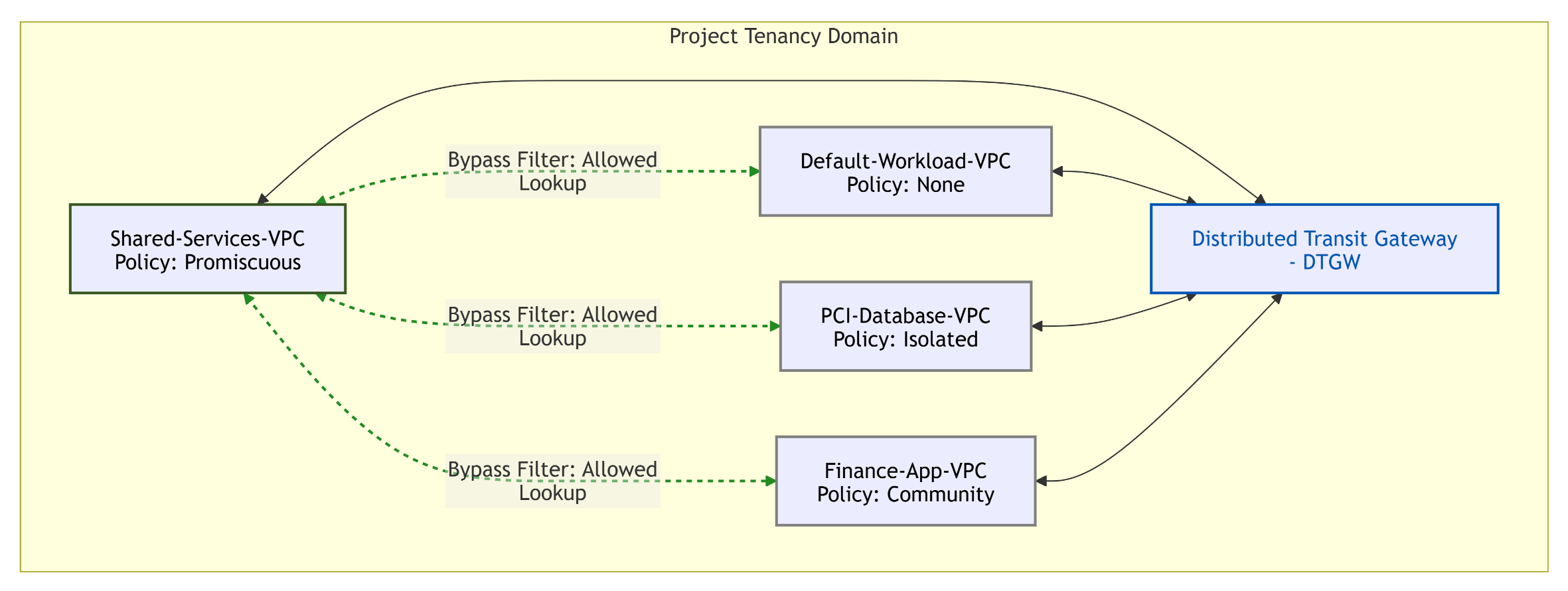
- Technical Logic: A VPC flagged as Promiscuous is granted an unrestricted, open routing posture. It is permitted to accept and establish routing lookups with every other VPC configured within the project domain, regardless of their assigned policy.
- Primary Use Case: Core shared infrastructure and common services tiers that require global visibility (e.g., housing Active Directory Domain Controllers, central enterprise DNS servers, configuration repositories, or backup targets that must be accessible by all application tiers).
C. Isolated Policy (Strict Zero-Trust)
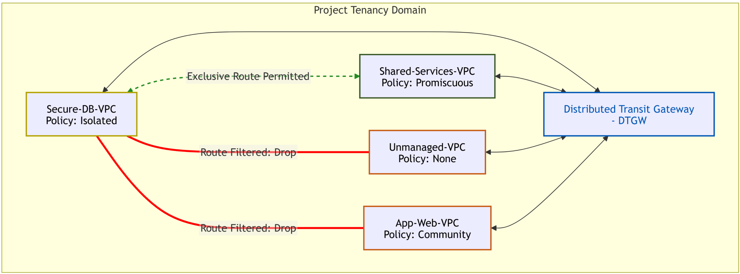
- Technical Logic: An Isolated VPC experiences strict route filtering. The logical routing fabric blocks the VPC from communicating with any standard or community-based VPCs inside the project. It is only allowed to route traffic to and from VPCs designated as Promiscuous.
- Primary Use Case: Strict Zero-Trust sandboxes, isolated development environments, PCI-DSS payment processing zones, or backend production database tiers that must prevent lateral network leakage while retaining access to central shared services like DNS and backups.
D. The “None” State (The Unmanaged Default)
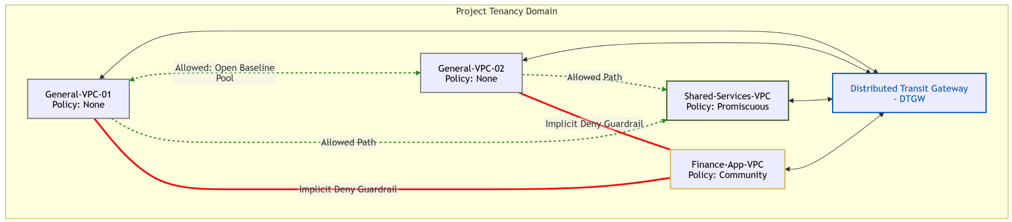
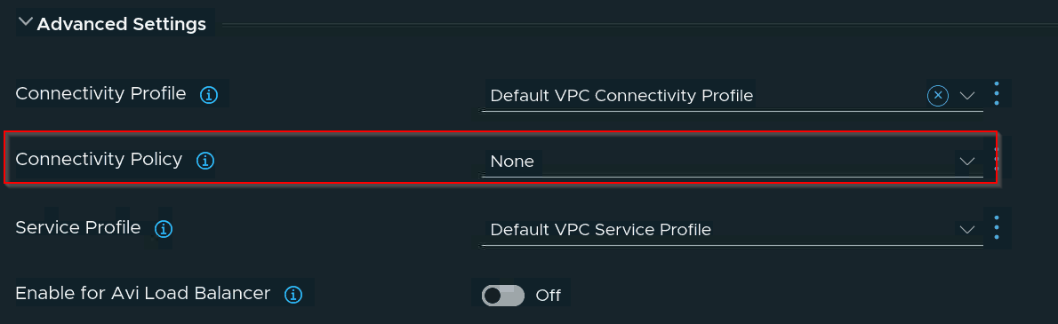
- Technical Logic: When a VPC’s Connectivity Policy is left unconfigured or set to None, it participates in an open baseline routing pool. It retains full communication capability with other None State VPCs and Promiscuous zones. However, the logical routing domain automatically enforces an implicit deny filter between None state VPCs and any explicitly isolated Community or Isolated groups.
- Primary Use Case: Out-of-the-box baseline networking for unclassified workloads, ensuring that creating a new default VPC cannot accidentally bridge into a protected tenant community.
VPC Connectivity Policy Matrix
| Connectivity Policy | Technical Logic (Data Plane Behavior) | Communication Scope (Allowed Traffic) | Enterprise Use Case |
| Community | Establishes group-based isolation by tagging routing tables with unique identifiers. The logical routing fabric drops traffic originating from outside the group. | Communicates freely with any VPC sharing the exact same Community String, as well as any Promiscuous VPCs. Blocked from all other zones. | Segregating multi-tier or multi-component line-of-business applications (e.g., allowing Finance-Web-VPC to route to Finance-App-VPC while completely air-gapping them from HR or Marketing networks). |
| Promiscuous | Enforces an open, unrestricted routing lookup posture across the entire project domain. It bypasses community and isolated boundary filters. | Communicates with every VPC configured within the project scope, regardless of whether those target VPCs have an assigned policy or a strict isolation boundary. | Core shared infrastructure and common services tiers that require global visibility (e.g., housing Active Directory Domain Controllers, central enterprise DNS servers, or backup repositories). |
| Isolated | Applies strict route-filtering and lookup constraints at the DTGW layer, preventing any localized routing table exchanges with neighboring tenant networks. | Communicates only with VPCs explicitly designated as Promiscuous. All other East-West cross-VPC traffic paths within the project are structurally dropped. | Strict Zero-Trust sandboxes, isolated development environments, PCI-DSS payment processing zones, or backend production database tiers that must prevent lateral network leakage. |
| None | Operates inside the default, unclassified routing pool. Enforces an implicit deny against incoming community tags while accepting untagged lookups. | Communicates with all other None state VPCs and any Promiscuous VPCs. Blocked from interacting with named Community or Isolated groups. | General-purpose, non-isolated tenant networks that do not map to specific regulatory or multi-tier compliance boundaries. |
Data Plane Mechanics: Line-Rate Efficiency and Scaling Boundaries
Edge-Bypassing Kernel Performance
A key factor behind the efficiency of VCF 9.1 Connectivity Control is its reliance on the Distributed Architecture Mode. Traditional multi-tenant routing boundaries required Tier-0/Tier-1 Edge cluster traversal to evaluate routing tables. Under VCF 9.1, these connectivity profiles are processed as native lookups inside the ESXi hypervisor kernel data plane.
Because this eliminates the requirement for centralized edge nodes, Tier-0 appliances, or upstream BGP route manipulation for basic tenant isolation, it bypasses physical fabric bottlenecks, providing near-wire-speed East-West transit latency.
Conversely, if a VPC is explicitly deployed in Centralized Mode (typically for specialized legacy stateful service insertion), traffic evaluation reverts to the Edge nodes, removing the kernel-level bypass benefit. Therefore, Distributed Mode is the recommended design baseline for scaling policy-driven tenant isolation.
Multi-Cluster and Multi-vCenter Span Limits
The operational span of these VPC connectivity policies is defined directly within the vCenter management plane. Depending on the underlying VCF software-defined data center (SDDC) architecture, administrators can define the boundary scope of the policy engine:
- Localized Cluster Boundary: Limits the synchronization of the routing lookup filters to a specific vSphere compute cluster.
- Global Domain Stretch: Dynamically scales across multiple vCenter instances bound to the same global VCF networking domain. This allows a
Communitypolicy string to seamlessly enforce isolation constraints even when member workloads are live-migrated (vMotioned) across physical cluster or vCenter boundaries.
Verifying Connectivity Control in vCenter
Phase 1: Applying Connectivity Policies in the vCenter UI
Capture 1: –
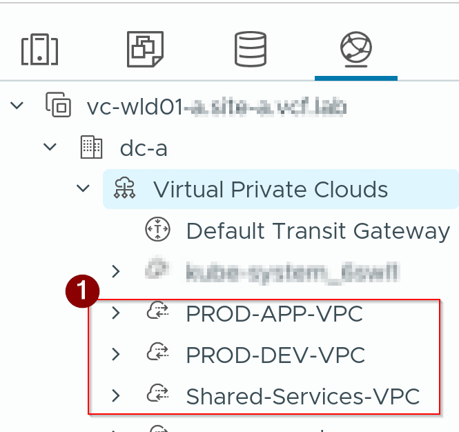
- We have 3 VPCs in action: PROD-APP-VPC, PROD-DEV-VPC, and Shared Services-VPC!
Capture 2: –
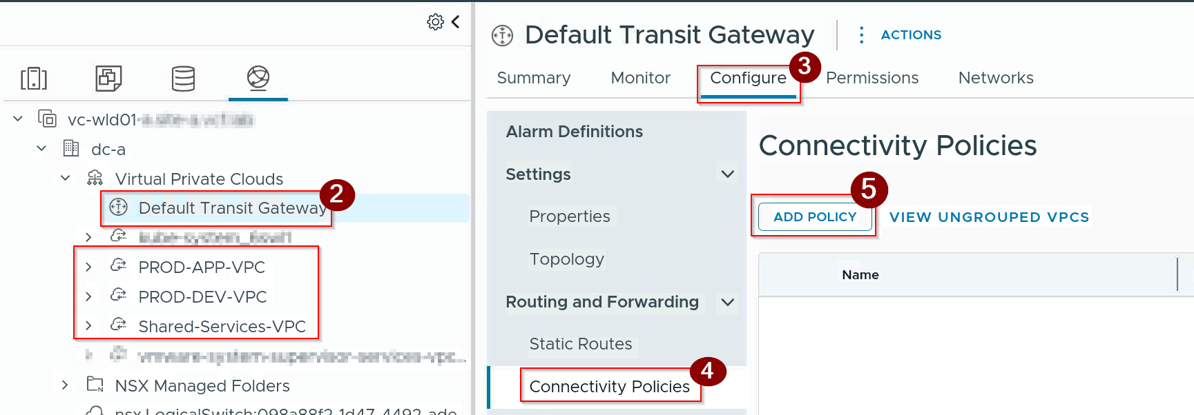
2. Click on Default Transit Gateway under Virtual private Clouds.
3. Click on Configure.
4. Click on Connectivity Policies under Routing and Forwarding.
5. Click on ADD POLICY.
Capture 3: –
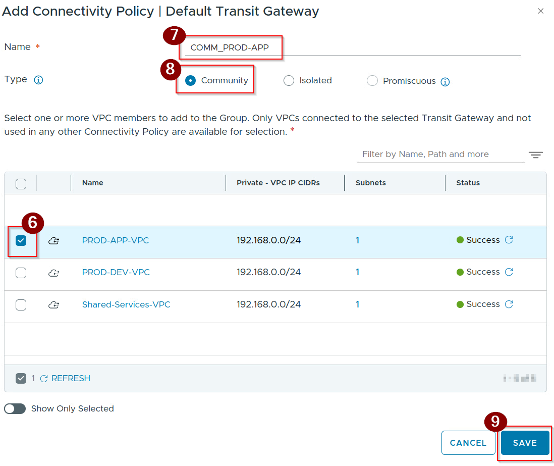
6. Select the VPC–> PROD-APP-VPC.
7. Give the Name–> COMM_PROD-APP.
8. Select the Type–> Community.
9. Click on Save.
Capture 4 :-
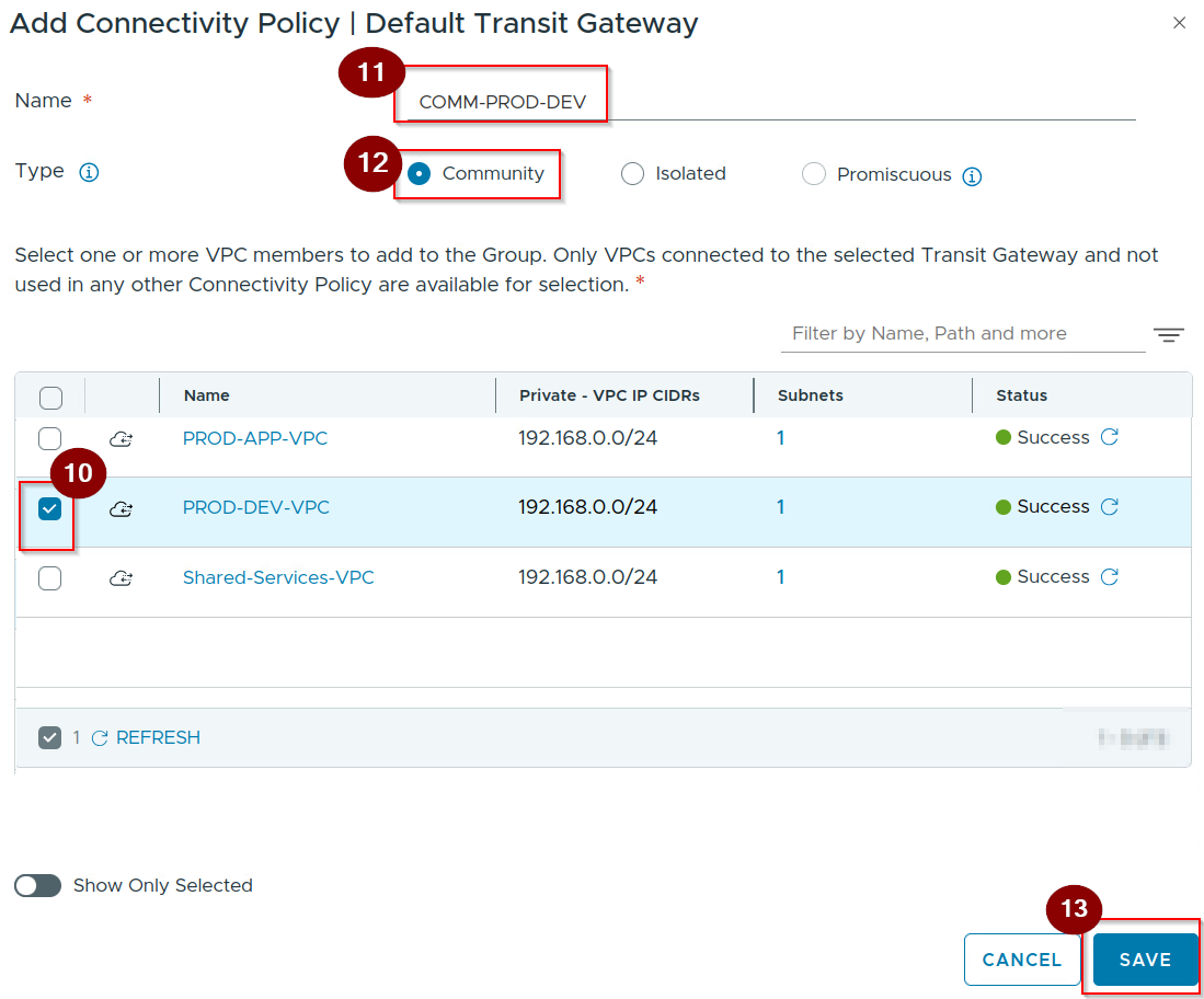
10. Select the VPC–> PROD-DEV-VPC.
11. Give the Name–> COMM-PROD-APP.
12. Select the Type–> Community.
13. Click on Save.
Capture 5: –
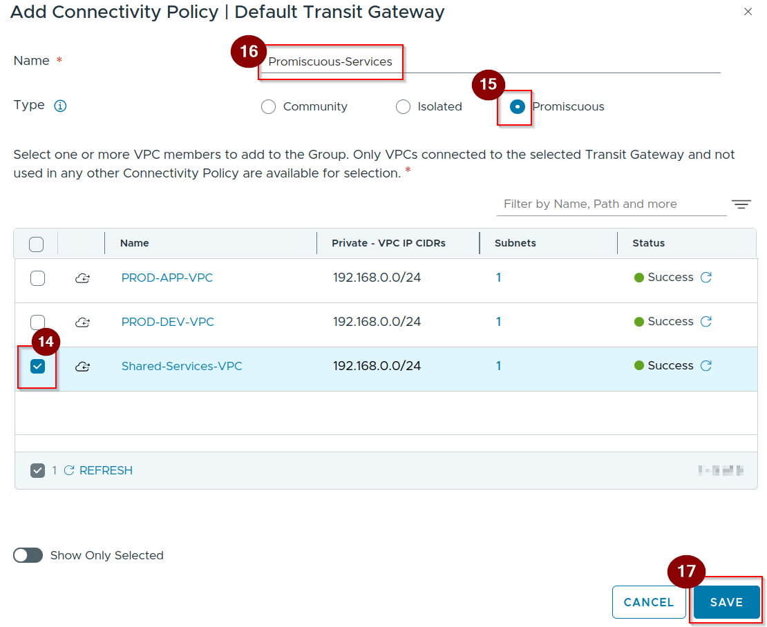
14. Select the VPC–> Shared-Services-VPC.
15. Select the Type–> Promiscuous.
16. Give the Name–> Promiscuous-Services.
17. Click on Save.
Capture 6: –
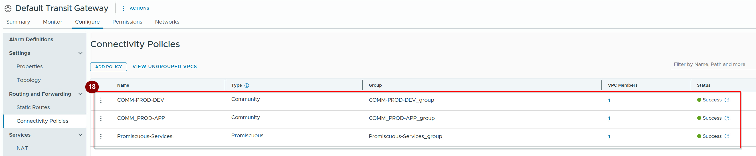
18. As we can see the connectivity profiles are successfully created.
Phase 2: Verifying Reachability via the Connectivity Dashboard
Capture 1:-
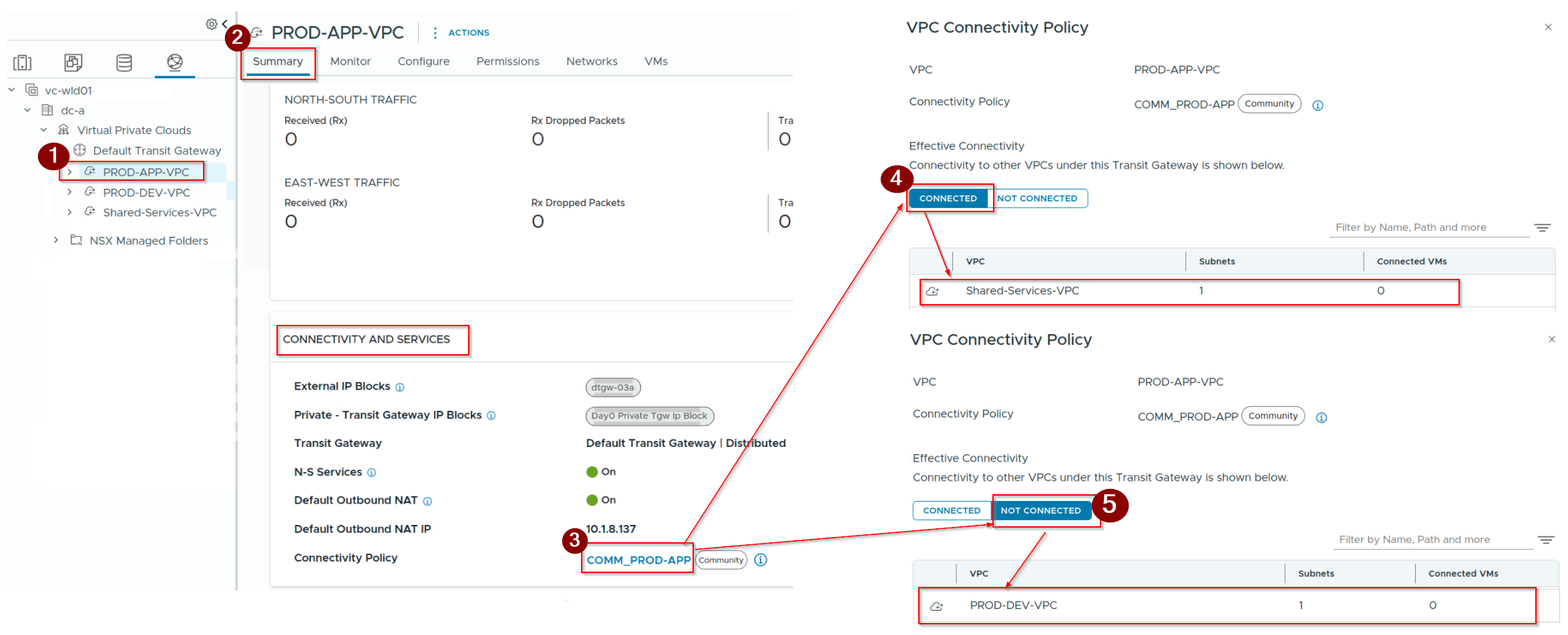
- Under Networking —> Click on VPC.
- Click on Summary.
- Click on connectivity policy.
- Under Connected we can see the Promiscuous-> Shared-Services-VPC shown.
- Under NOT Connected we can see the Community–> PROD-DEV-VPC shown.
Enter the Host-Level NSX CLI Wrapper
Capture 1: –

- Connect via SSH to the ESXi host where your target tenant Virtual Machines (such as your PROD-APP or DEV workloads) are actively running.
- Log in using your root or administrative credentials.
- Launch the native NSX command-line environment by entering:
- run the command “get vpcs“
Capture 2 :-

Run the command
“get vpcs /orgs/default/projects/<Project-ID>/vpcs/<VPC Name> connectivity-policy“
or
“get vpcs /orgs/default/projects/<Project-ID>/vpcs/<VPC Name> connectivity-policy–workload“
The terminal will return a structured data matrix outlining exactly how the routing engine treats traffic entering and exiting that logical workspace. Look directly under the Policy id, Connectivity Scope , VM IPs column to verify the status.
Conclusion
VPC Connectivity Control in VCF 9.1 represents a fundamental improvement in how on-premises multi-tenant environments are engineered. By moving structural traffic isolation down to the logical routing layer, architects no longer need to depend on complex firewall policy design for basic day-1 network separation.
Utilizing intuitive Promiscuous, Isolated, and Community classification boundaries allows infrastructure teams to achieve robust multi-tenant air-gapping natively inside the vCenter interface. This keeps the vDefend Distributed Firewall completely uncluttered, ensuring that host CPU resources are spent on deep application micro-segmentation and advanced threat prevention rather than simple network-blocking tasks.


Leave a Reply