

- Introduction
- Feature Progression: VCF 9.0 vs. VCF 9.1 EVPN Architecture
- Control Plane Mechanics: The Interface-less IP-VRF Processing
- Physical Interoperability & Platform Deployment Prerequisites
- Deployment Runbook
- Conclusion
Introduction
Standardized BGP-EVPN VXLAN fabrics are crucial for multi-tenant isolation, scale, and performance across physical underlays Historically, VMware Cloud Foundation (VCF) relied on Centralized Transit Gateways (CTGW), which introduced two primary architectural constraints :
Edge Node Bottlenecks: All North-South routing hairpined through specialized NSX Edge Node clusters, creating distinct operational choke points.
Scale & Boundary Limits: Traditional Distributed Transit Gateways (DTGW) using Distributed VLAN Connections were bound to 4,094 VLAN IDs, suffered heavy Broadcast, Unknown Unicast, and Multicast (BUM) traffic overhead as subnets grew, and lacked dynamic routing protocol elasticity.
VMware Cloud Foundation (VCF) 9.1 addresses these limitations with native BGP-EVPN VXLAN data plane integration for DTGWs. By leveraging containerized Virtual Network Appliances (VNA) acting as VCF Route Controllers, workloads peer directly with physical Border Gateways (BGW) to deliver host-local, decentralized North-South routing with zero reliance on legacy edge hardware bottlenecks.
Note:- IF you want to know What is VNA, its Use Cases and deployment foundational Steps follow the link here :- https://puneetsharma.blog/2026/05/18/vcf-9-1-nsx-technical-deep-dive-implementing-distributed-transit-gateways-dtgw-and-vna-clusters/
https://puneetsharma.blog/2026/07/06/edge-less-north-south-routing-vna-driven-l3-evpn-type-5-integration-with-vcf-9-1-dtgw/
https://puneetsharma.blog/2026/07/15/goodbye-edge-bottlenecks-vcf-9-1-delivers-line-rate-stretched-l2-networks-via-vna-distributed-bridging/
Feature Progression: VCF 9.0 vs. VCF 9.1 EVPN Architecture
The integration of BGP-EVPN topologies evolved across the major VCF version releases:
| Architectural Metric | VCF 9.0 EVPN Framework | VCF 9.1 Distributed EVPN Fabric |
| Routing Topography | Centralized Transit Gateway (CTGW) only. | Distributed Transit Gateway (DTGW) with native VXLAN encapsulation. |
| Data Path Pathing | North-South traffic must traverse a centralized NSX Edge Node cluster. | Edge-less, host-local forwarding. Traffic encapsulates directly at the hypervisor layer to the physical underlay. |
| Control Plane Mechanism | Standard BGP peering directly bound to Edge Node uplink interfaces. | VNA-based Route Controllers handle MP-BGP EVPN control plane exchanges. |
| Data Path Scalability | Bounded by physical Edge Node throughput limitations. | Leverages the distributed VTEP MAC footprint of the ESXi hypervisor cluster. |
Control Plane Mechanics: The Interface-less IP-VRF Processing
Capture 1: –
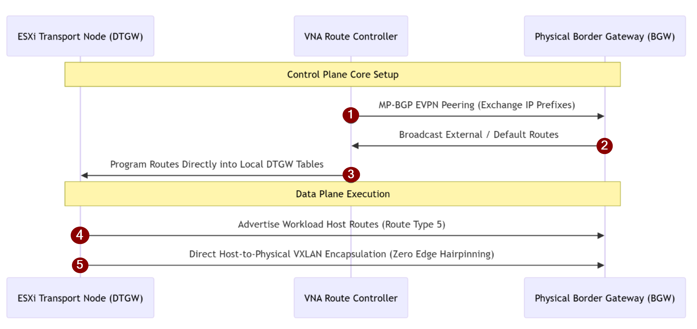
Within this model, the L3 EVPN Protocol Execution 5-Step Core Macro Workflow detailed below:
| Step | Operation Phase | Technical Description & Protocol Action |
| 1 | MP-BGP EVPN Prefix Exchange | The VNA Route Controller establishes an MP-BGP EVPN peering session to exchange tenant network reachability and IP prefixes directly with the physical Border Gateways. |
| 2 | External & Default Route Learning | The physical underlay fabric dynamically broadcasts external network paths and default routes back to the receiving VNA. |
| 3 | Local Table Programming | The VNA processes these learned routing paths and programs them straight down into the local forwarding tables of the distributed transit gateways. |
| 4 | Workload Host Route Advertisement | To resolve distributed macro-locations, the DTGW advertises highly specific workload host routes (/32 for IPv4 or /128 for IPv6) as Route Type 5 directly to the BGW. |
| 5 | Host-Local VXLAN Encapsulation | The host DTGW leverages programmed default routes to encapsulate virtual machine frames into EVPN-compliant VXLAN tunnels right at the hypervisor layer, forwarding traffic directly to the physical BGW and bypassing edge nodes completely. |
Physical Interoperability & Platform Deployment Prerequisites
| Target System / Boundary | Core Technical Prerequisite & Constraint | Operational Impact |
| Arista Network Fabrics | Requires 7000R Series (Jericho+ architectures) running EOS 4.33 or later. | Mandated for physical Border Gateway (BGW) capabilities. Click Here |
| Cisco Nexus Fabrics | Requires Nexus 9000 FX Series or later running NX-OS 10.5 or later. | Supported in NX-OS Mode only; ACI Mode is completely unsupported. Click Here |
| VXLAN Layer 3 Underlay | Requires full bidirectional VTEP routing between ESXi and physical spine-leaf VTEPs. | Critical to maintaining the VXLAN data plane loop. Click Here |
| Routing Parameter Sync | BGP ASN, L3VNI, and RD/RT values must be pre-configured on physical switches. | Pre-flight validation required before configuring VCF. Click Here |
| Connection Topologies | Implements a strict 1:N mapping from VNA to DTGW ; maximum one VXLAN uplink per DTGW. | Prevents overlapping multi-path routing bounds within a single DTGW. Click Here |
| VLAN Separation | The VNA cluster must be dedicated to this role, peering over an isolated VLAN hidden from the tenant DTGW layer. | Isolates global control plane peering traffic from tenant-level visibility. Click Here |
Deployment Runbook
Phase1:- Provision the VCF Route Controller with Dedicated VNA Cluster
Capture 1: –
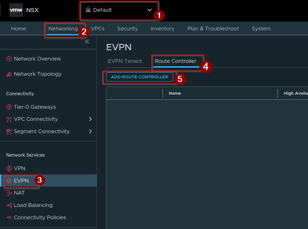
- Select the default.
- Click on Networking.
- Click on EVPN under network Services.
- Click on Route Controller.
- Click on ADD Route Controller.
Capture 2: –
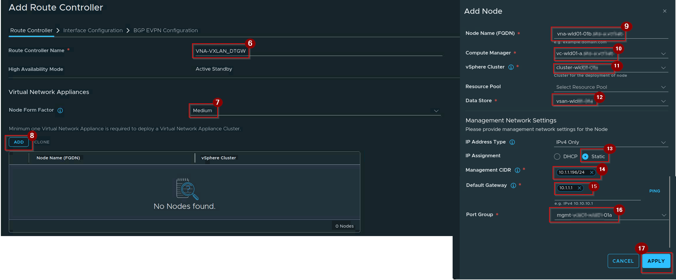
6. Give the name of Route Controller.
7. Select the form factor.
Note : You will find only Small and Medium option not the L or XL.
Large & XL Form Factors: Reserved strictly for resource-intensive, in-line data services (like L4/L7 Load Balancing or stateful NAT) that must physically process active workload traffic.
Medium Form Factor: More than enough for the Route Controller because it handles 0% of actual data plane packets, requiring minimal overhead just to manage BGP tables and push routes down to the hypervisors.
8. Click on ADD.
9. Give the Node Name.
10. Select the Compute Manager.
11. Select the vSphere Cluster.
12. Select the data Store.
13. Select the IP Assignment.
14. Give the Management IP.
15. Give the Default Gateway.
Note:- Click on ping to check the connectivity.
16. Select the Port Group.
17. Click on Apply.
Capture 3: –
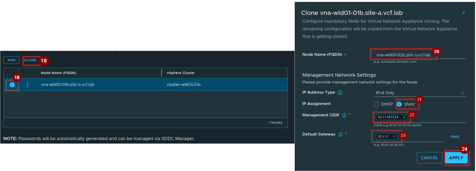
18. Click on radio Button of First Route Controller.
19. Click on Clone.
20. Give the Node Name.
21.Select the IP Assignment.
22.Give the Management IP.
23.Give the Default Gateway.
Note:- Click on ping to check the connectivity.
24. Click on Apply.
Capture 4: –
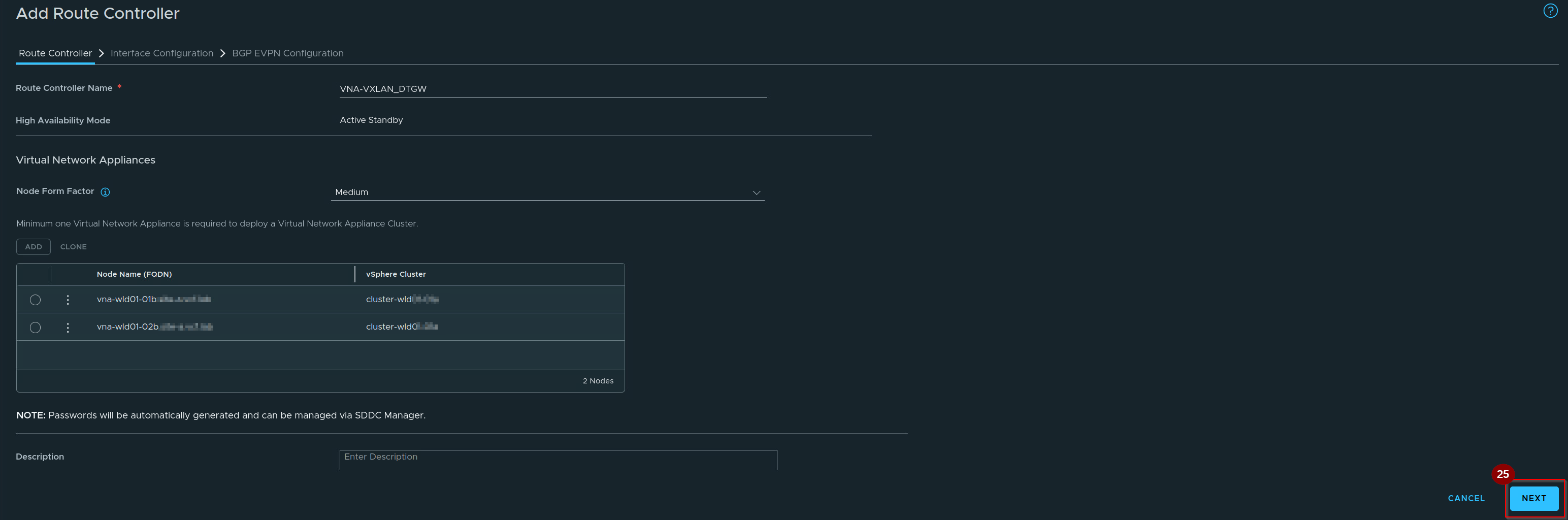
25. Click on Next.
Capture 5: –
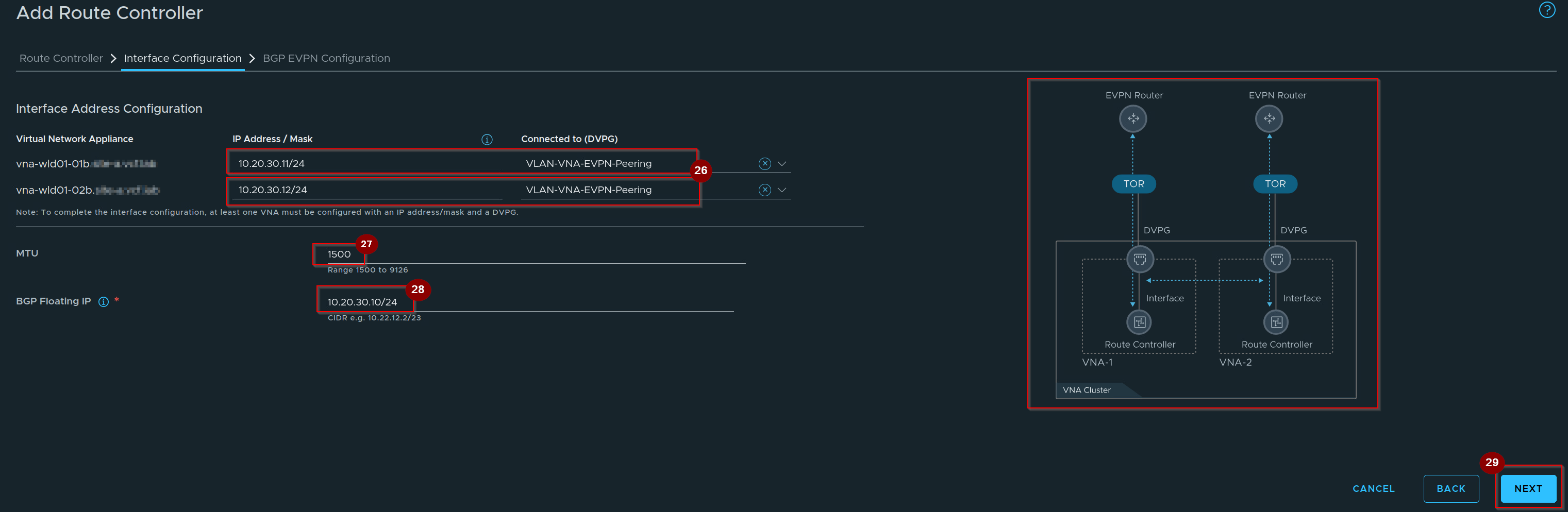
26. Unique physical uplink IP for VNA Appliance Node 1 & Node 2 (for HA).
27. Give the MTU.
28. Give the BGP Floating IP.
Note :- The BGP Floating IP acts as a shared Virtual IP (VIP) across a high-availability pair of VNA appliances, ensuring the physical switches only have to peer with a single routing identity. If one VNA appliance fails or reboots, the Floating IP instantly shifts to the surviving node, preventing the BGP session from dropping and keeping network traffic running without interruption.
29. Click on Next.
Capture 6: –
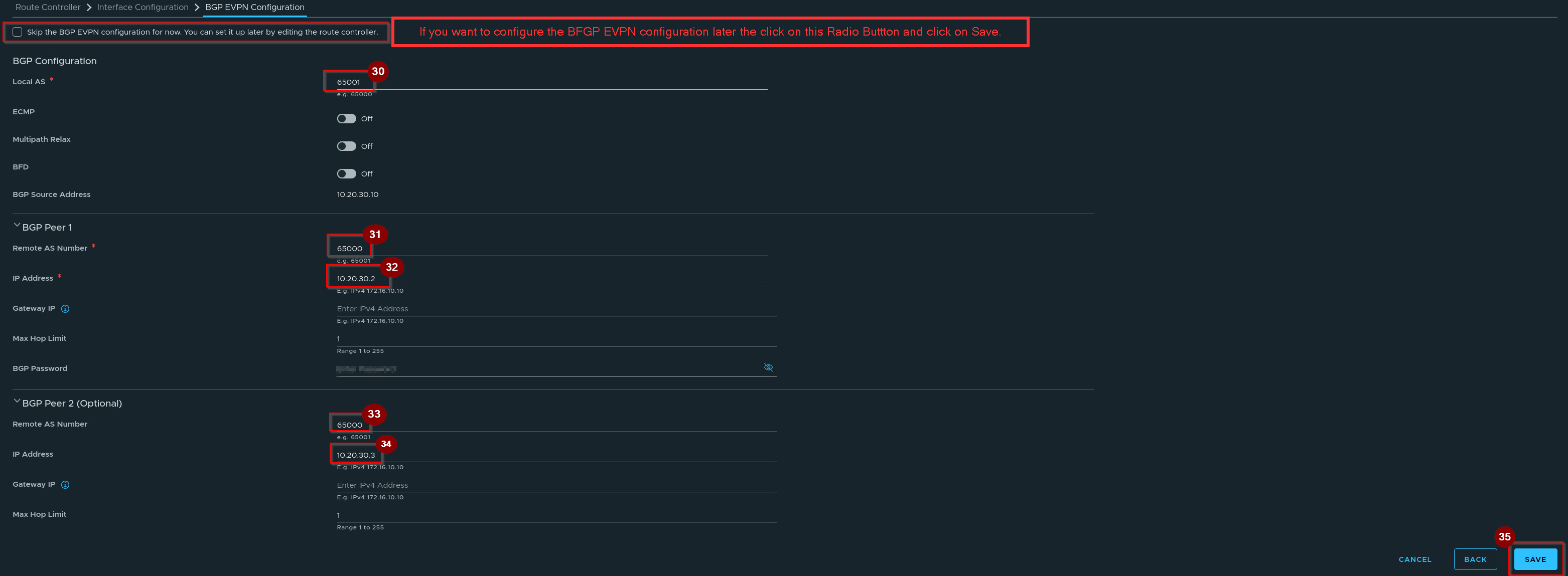
30. Give the Local AS Number.
31. Give the Remote AS number.
32. Give the Peer IP Address.
33. Give the Remote AS number.
34. Give the Second Peer IP Address.
35. Click on Save.
Capture 7:-
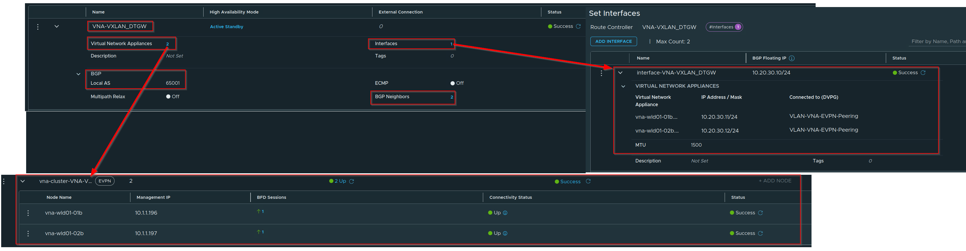
Note:- VNA Cluster has Successfully created. This process (Initializes, Deploy & UP)will usually take 20 to 25 mins. One segment interface will automatically created.
Phase 2:- Configure a Distributed VXLAN Connection
Capture 1:-
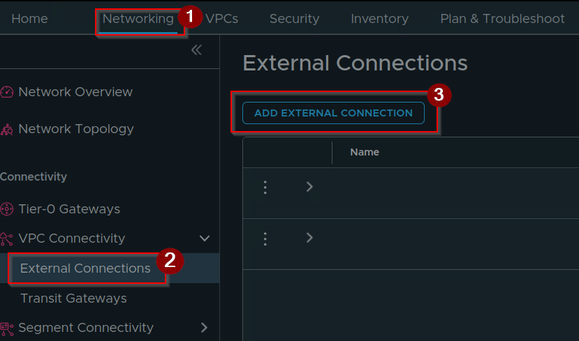
- Click on Networking.
- Click on External Connections.
- Click on ADD EXTERNAL CONNECTIONS.
Capture 2: –
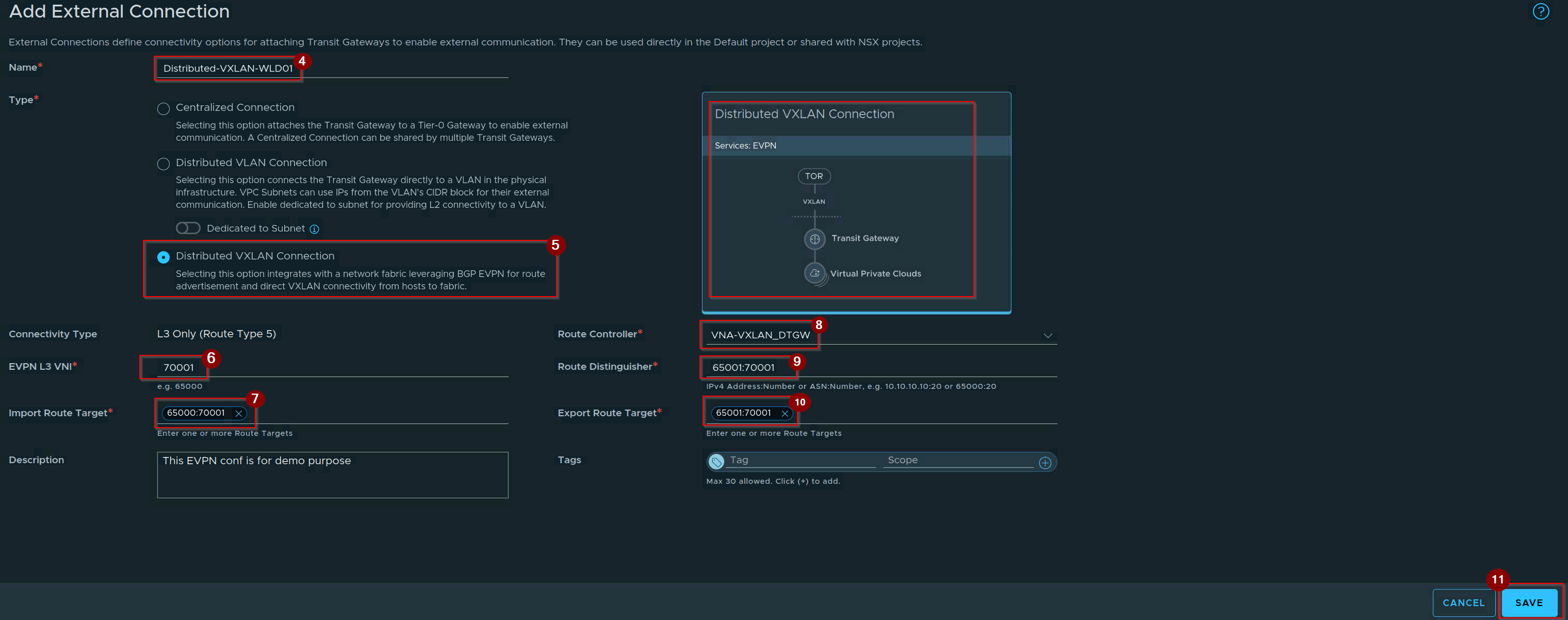
4. Give the Name of External Connection.
5. Click on Radio Button of Distributed VXLAN Connection.
6. Give the EVPN L3 VNI ID.
7. Give the Import Route Target ID.
8. Select the Route Controller.
9. Give the Route Distinguisher ID.
10. Give the Export Route Target.
11. Click On Save.
Note:- Deciphering the ASN-to-VNI Mapping Syntax
When configuring a Distributed VXLAN Connection, VCF uses the industry-standard [ASN]:[VNI] format to map the control plane routing tags to the data plane network segment:
Route Targets (Import 65000:70001 / Export 65001:70001): Controls the routing policy. The Export RT tags outbound routes with the local VNA identity (65001), while the Import RT selectively pulls in Type 5 routes broadcasted by the physical Border Gateway’s remote ASN (65000), ensuring completely symmetric path paths.
The Segment Anchor (L3 VNI – 70001): This is the distinct Layer 3 Virtual Network Identifier that defines the tenant’s isolated data plane routing matrix across the physical fabric.
Route Distinguisher (RD – 65001:70001): Maps the local VNA Autonomous System Number (65001) directly to the VNI (70001). This adds a unique prefix to the advertised paths so the BGP table never mixes up overlapping IP spaces from different tenants.
Capture 3:-

Note:- External Connection is Successfully Configured.
Phase 3: Configure the Tenant Distributed Transit Gateway
Capture 1:-
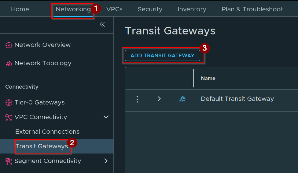
- Click on Networking.
- Click on Transit Gateways.
- Click on ADD TRANSIT GATEWAY.
Capture 2: –
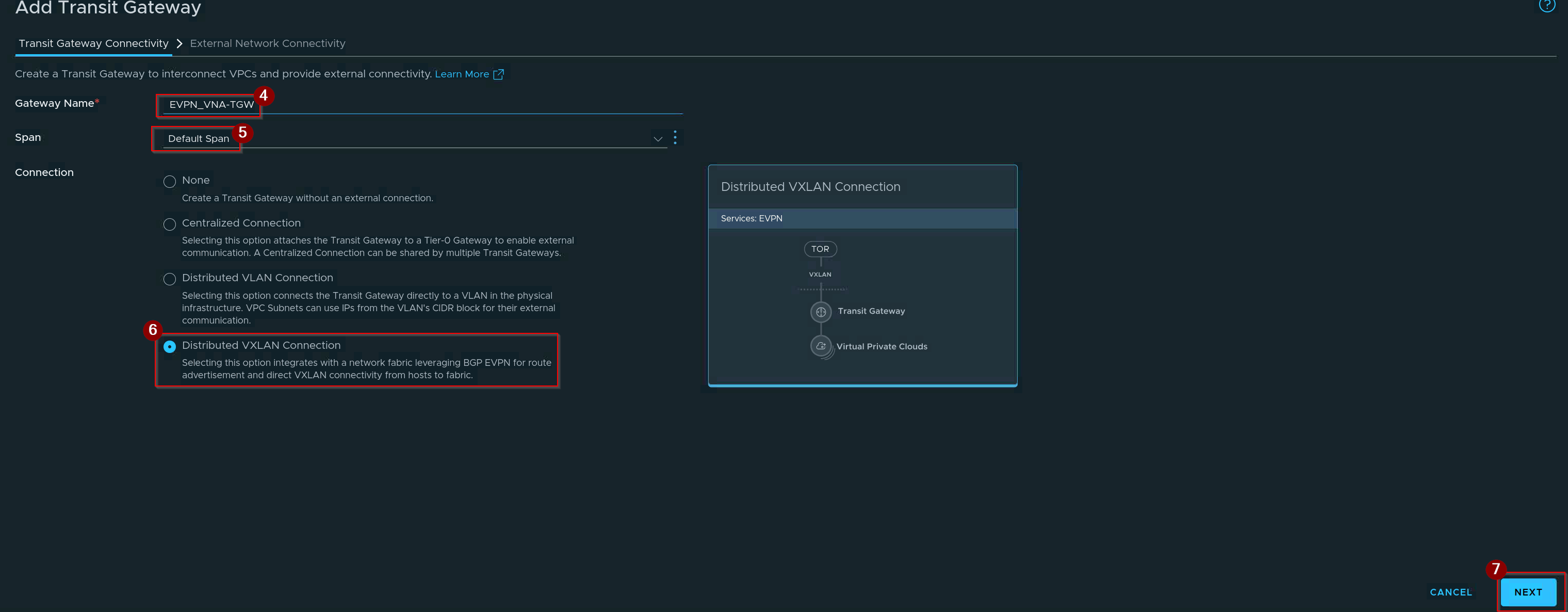
4. Give the name of TGW.
5. Select the Span.
6. Click on Radio Button in front of Distributed VXLAN Connection.
7. Click on Next.
Capture 3: –
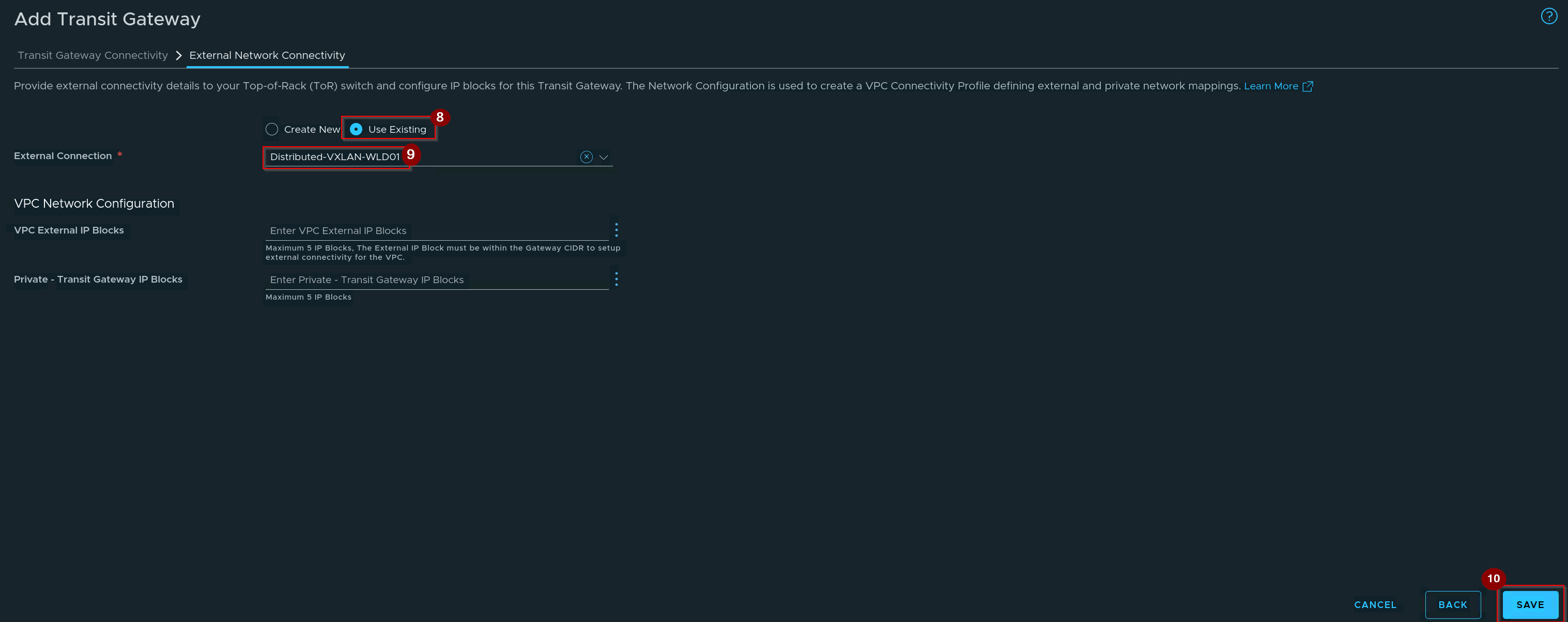
8. Click on Use Existing Radio Button.
9. Select the External Connection.
10. Click On Save.
Capture 4: –
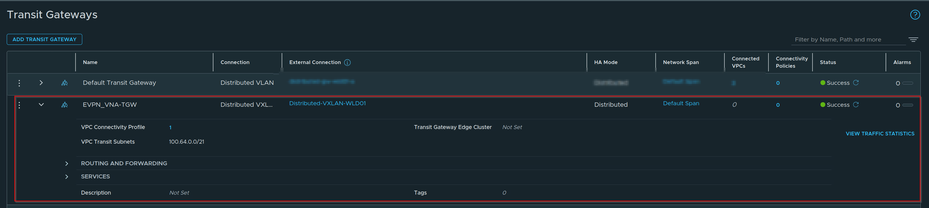
TGW is Successfully Configured.
Phase 4: Establish the VPC and Custom Connectivity Profile
Capture 1: –
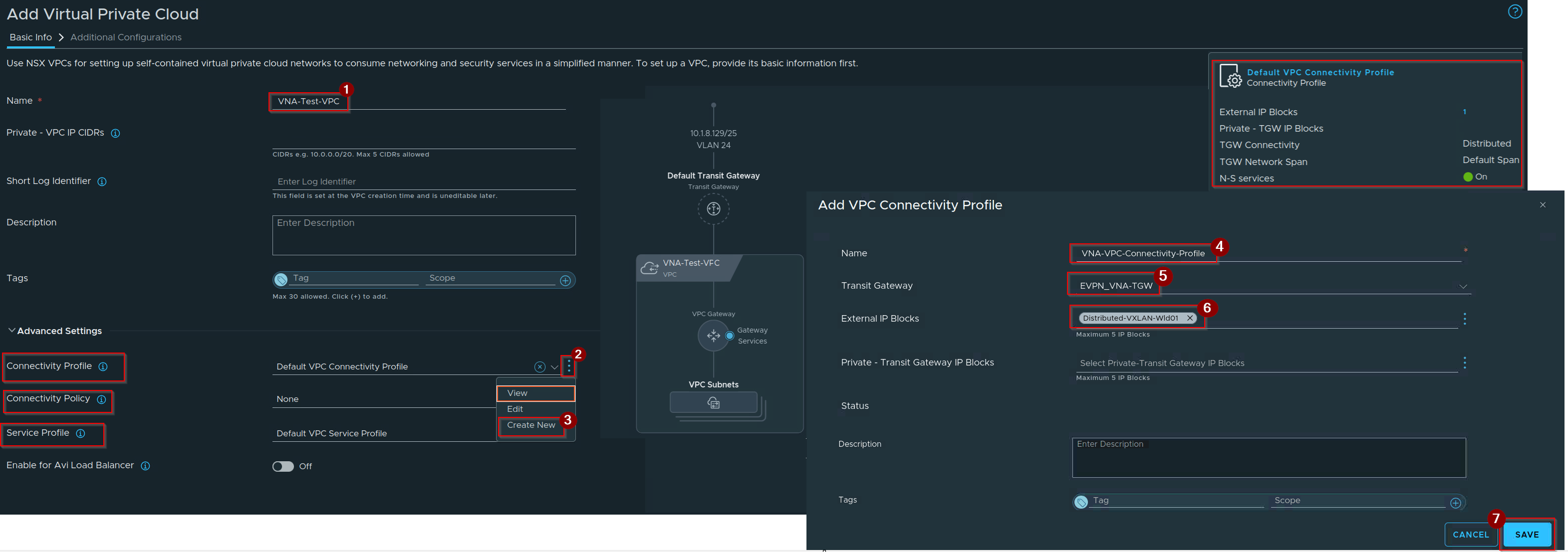
Select the Project–> Navigate to VPCs–> Click on Virtual Private Cloud–> Click on ADD VPC.
1. Give the Name of VPC.
2. Under Advance setting click on 3 dots of Connectivity profile.
3. Click on Create New.
4. Give the Name of the Connectivity profile.
5. Select the Transit Gateway.
6. Select the External IP Blocks.
7. Click on Save.
Capture 2: –
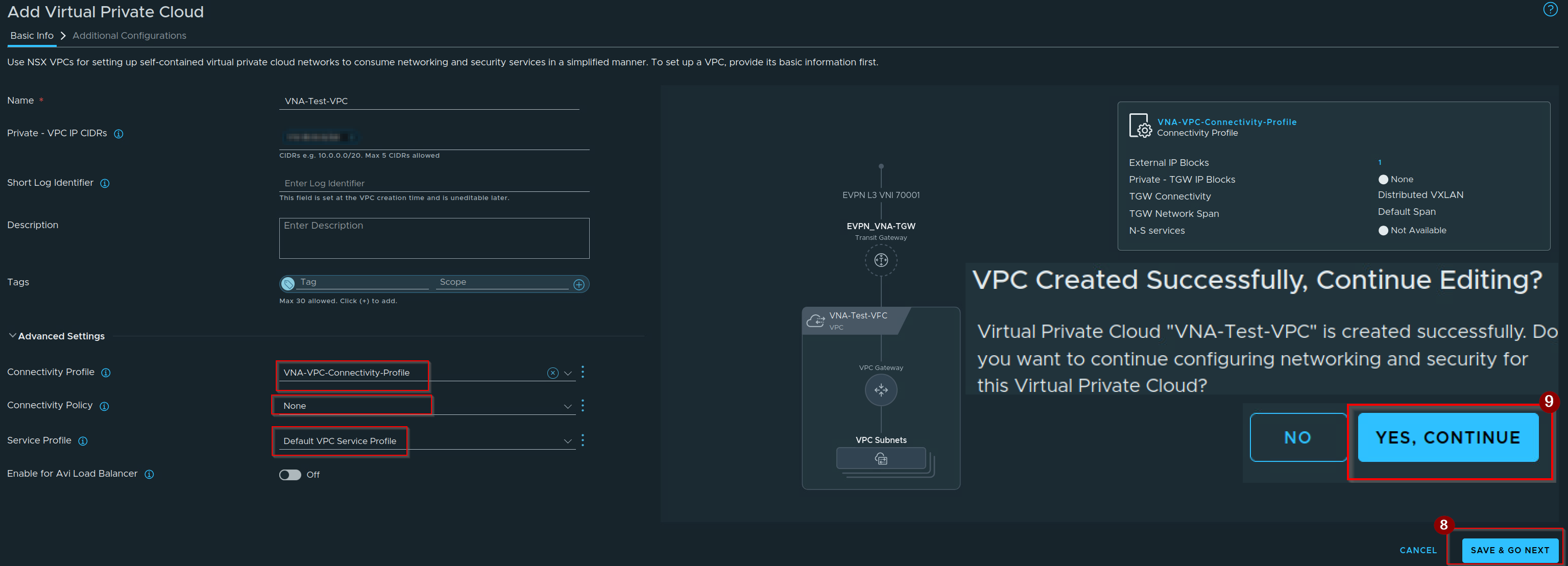
8. Click on Save & GO Next.
9. Click on Yes, Continue.
Capture 3: –
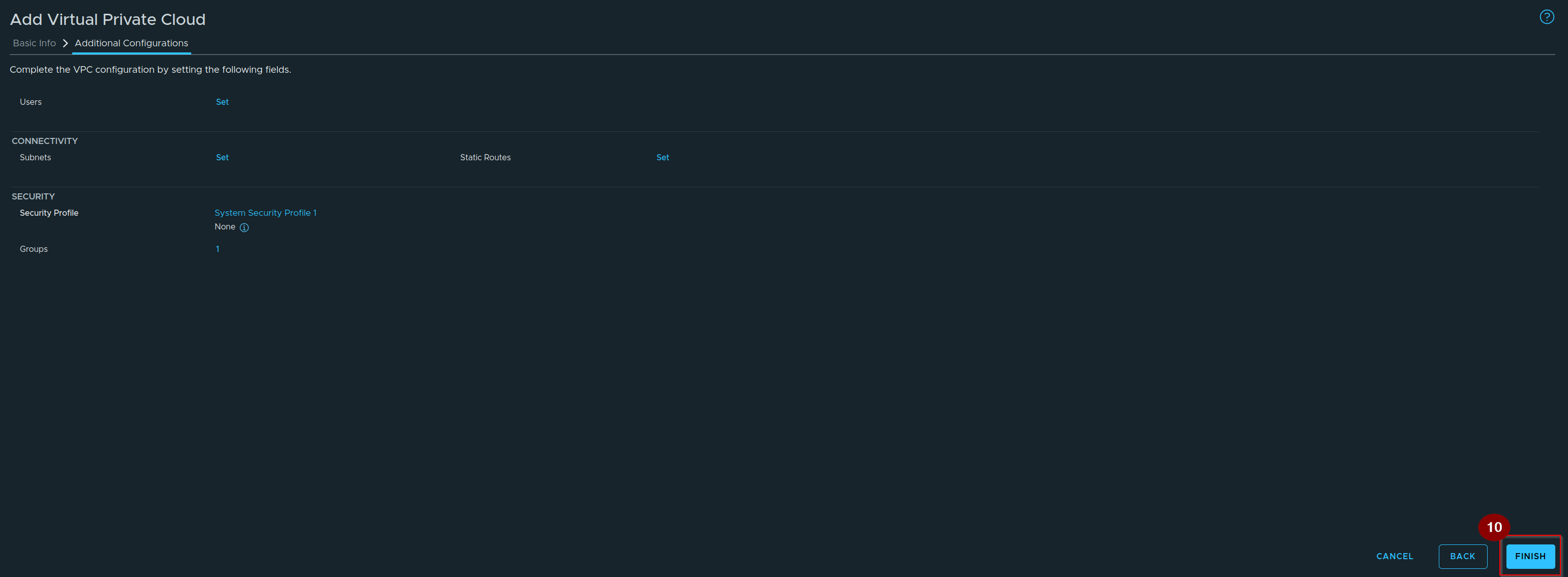
10. Click on Finish.
Capture 4: –
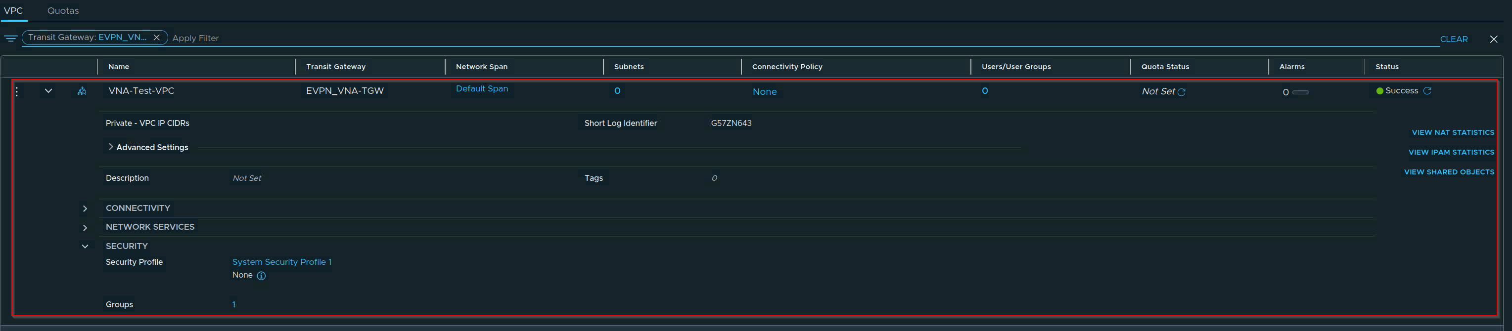
VPC is successfully configured.
Phase 5: Technical Verification
Capture 1:-
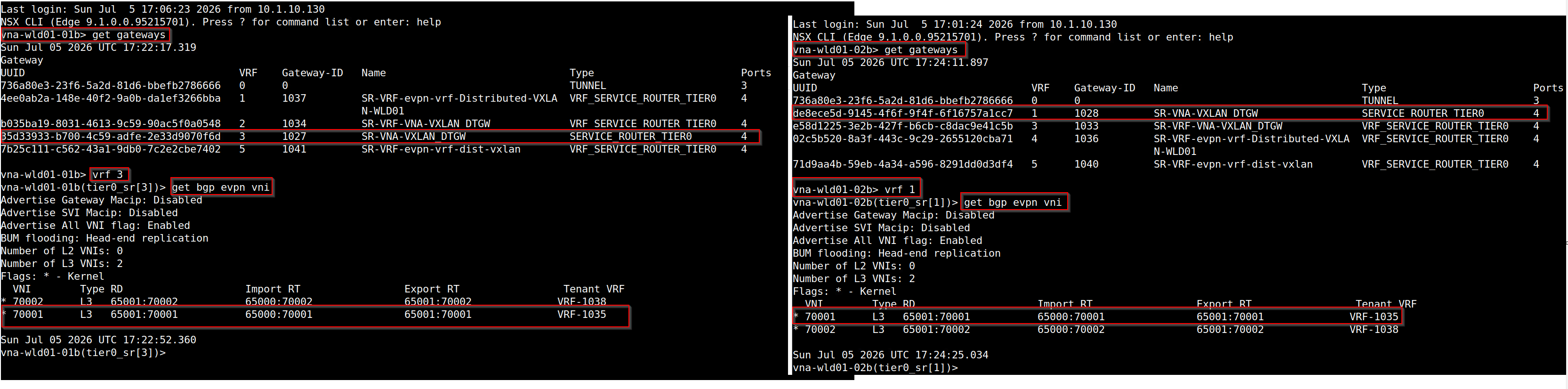
Once the deployment phase is completed, the data plane routes traffic dynamically without relying on centralized edge processing hops:
Workload Ingress Acceleration: When a virtual machine on a VPC subnet generates a packet destined for external assets, the packet maps directly to the host-local VPC Distributed Router (DR).
Control Plane Injection: The VNA Route Controller receives external default or specific routes from the BGW and programs them directly into the hypervisor’s local DTGW engine.
Host-Local Encapsulation: The local DTGW leverages default routes programmed by the VCF Route Controller to encapsulate the ethernet frame directly into an EVPN-compliant VXLAN tunnel right at the hypervisor layer. It bypasses external edge appliances entirely, forwarding the payload directly to the physical BGW via the host’s native VTEP interface.
Conclusion
The implementation of VNA-driven BGP-EVPN Route Control Integration with Distributed Transit Gateways inside VCF 9.1 represents a fundamental modernization of private cloud network fabrics. Moving from edge-anchored centralized routing to an interface-less, distributed Layer 3 EVPN architecture removes physical throughput bottlenecks and isolates runtime fault domains. By using dedicated, containerized VNA Route Controllers to handle dynamic control planes , enterprise infrastructure teams can deploy self-service, highly scalable multi-tenant networks that integrate seamlessly with core data center switching architectures.
Stay tuned! In our next technical installment, we will detail VNA Use Case 2: Multi-Tenant Edge-less Services.


Leave a comment