

The Core Pain Point: Centralized Bridging Bottlenecks
The Architectural Challenge
- The Operational Necessity: Data center consolidations frequently require stretching existing physical Layer 2 broadcast domains into the SDDC to completely eliminate complex, high-risk workload Re-IP workflows.
- The Legacy Legacy Edge Path: Historically, VCF mandated Centralized NSX Edge Bridges. Stretched traffic was forced to leave the source ESXi host, traverse the physical fabric to a specific virtual Edge Node appliance, execute user-space DPDK bridging operations, and hairpin back out to the destination segment.
- The Performance Cap: This centralized data-plane architecture introduced severe packet latency, created a critical infrastructure chokepoint, and strictly capped throughput to virtual appliance processing boundaries (10–40 Gbps).
The VCF 9.1 Solution: Out-of-Path Distributed Bridging
- VCF 9.1 decouples Layer 2 extension services from the virtual Edge Node tier via VLAN Extension for VPC Subnets, shifting orchestration entirely out-of-path to a containerized Virtual Network Appliance (VNA) cluster.
- Data Plane Execution: Instead of hairpining traffic through a centralized gateway, the architecture instantiates a native, host-local in-kernel distributed bridge (
dbridge) module within the ESXi hypervisor layer of every participating transport node. - Control Plane Management: The VNA cluster operates exclusively as a control-plane manager, provisioning a Distributed Logical Connection (DLC) that maps the physical VLAN directly to an isolated VPC overlay subnet.
Performance & Resource Dividends
- Wire-Speed Scaling: Shifting bridging operations into the hypervisor kernel enables true Edge-less Layer 2 extensions. Stretched workloads communicate natively at the physical line-rate of the host pNICs, enabling high-throughput performance scaling across the fabric.
- Compute Reclamation: Eliminating resource-heavy user-space DPDK polling loops reclaims significant host vCPU and RAM overhead, returning that raw compute capacity directly to the cluster to run production tenant virtual machines.
Note:- IF you want to know What is VNA, its Use Cases and deployment foundational Steps follow the link here :- https://puneetsharma.blog/2026/05/18/vcf-9-1-nsx-technical-deep-dive-implementing-distributed-transit-gateways-dtgw-and-vna-clusters/
https://puneetsharma.blog/2026/07/06/edge-less-north-south-routing-vna-driven-l3-evpn-type-5-integration-with-vcf-9-1-dtgw/
https://puneetsharma.blog/2026/07/15/goodbye-edge-bottlenecks-vcf-9-1-delivers-line-rate-stretched-l2-networks-via-vna-distributed-bridging/
The Modern Fix: VNA-Driven Distributed Bridging (dbridge)
VCF 9.1 decouples Layer 2 extension services from the virtual Edge Node tier, shifting orchestration out-of-path to a containerized Virtual Network Appliance (VNA) cluster.
Data Plane: Instead of hairpining traffic through a centralized gateway, the architecture instantiates a native, host-local in-kernel distributed bridge (dbridge) module within the ESXi hypervisor layer of each participating transport node.
Control Plane: The VNA operates exclusively as a control plane manager, provisioning a Distributed Logical Connection (DLC) that maps the physical VLAN directly to an isolated VPC overlay subnet.
Operational Impact & Resource Optimization
| Architectural Vector | Centralized Legacy Bridging | VCF 9.1 VNA Distributed Bridging (dbridge) | Engineering & Resource Impact |
| Data Plane Pathing | In-Line Centralization: Stretched packets are forced to traverse physical links to a specific virtual Edge Node cluster. | Edge-less Localization: 0% of data-plane traffic passes through the VNA VMs or standard Edge Nodes. | Eliminates Chokepoints: Removes latency overhead caused by traffic hairpining out to edge clusters. |
| Throughput Performance | Appliance Bounded: Throughput is strictly capped by the vCPU, vNIC, and DPDK capacities of the virtual Edge. | Wire-Speed Capable: Traffic switches natively at the hypervisor boundary. | Line-Rate Scaling: Performance scales directly with the speed of the physical host pNICs (100Gbps+ fabrics). |
| Host Resource Allocation | Heavy & High Overhead: Requires dedicated, large Edge appliance compute footprints running intensive packet loops. | Near Zero Overhead: VNA cluster manages mapping tables out-of-path, utilizing negligible kernel resources. | Compute Reclamation: Reclaims valuable host vCPU and RAM, returning that capacity directly to tenant compute workloads. |
Operational Modes: Public vs. Dedicated
When establishing a VLAN extension, engineers must choose between two distinct structural modes based on routing authority:
| Operational Metric | Public VLAN Extension Subnet (L2 Subnet Use Case) | Dedicated Distributed VLAN Connection (L3 Subnet Use Case) |
| Routing Authority | External Physical Router. | Internal VCF VPC Gateway. |
| VPC Gateway Status | Explicitly disconnected from the internal VPC logical gateway. | Active connected interface inside the tenant VPC routing table. |
| Supported Fabric Bindings | Works across all Transit Gateway (TGW) types. | Supported exclusively for Distributed TGWs (DTGW). |
| East-West Tenant Access | Traffic bound for other subnets within the same VPC must hairpin out to the external physical router and return. | Traffic routes natively and locally across internal VPC subnets at line-rate. |
| Data Plane Reachability | Layer 2 traffic between the virtual overlay and physical underlay switches seamlessly without a centralized Edge choking point. | Underlay workloads can access peer underlay segments and reach VPC Public subnets. Overlay workloads gain full access to the internal VPC topology. |
| Primary Migration Value | Onboarding legacy workloads while retaining their original, authoritative physical default gateway. | Final-stage cutovers where the network segment shifts to VCF control, ensuring live migrations experience zero traffic disruption. |
Infrastructure Prerequisites & Scale Boundaries Matrix
| Target Layer | Technical Requirement | Operational Design Boundary & Enforcement |
| Control Plane Sizing | Medium Form Factor Profile | VNA clusters must run a Medium sizing template in an Active/Standby High Availability pair to process mapping databases safely. |
| Physical Underlay Trunking | Trunk-Allowed Target VLANs | Target legacy VLAN IDs must be explicitly permitted across the physical ToR leaf switch interfaces connected to ESXi pNICs. |
| Hardware Capabilities | Validated Driver Offloads | Host pNIC hardware drivers must be certified to execute native overlay-to-VLAN kernel encapsulation switching locally. |
| Loop Prevention | Strict 1:N Topology Bound | A single physical VLAN can be mapped to exactly one VPC subnet instance to prevent catastrophic hardware spanning-tree loops. |
The Packet Mechanics: Traffic Flow & Flood Optimization
Stretching Layer 2 domains introduces the risk of Broadcast, Unknown Unicast, and Multicast (BUM) traffic storms. VCF 9.1 mitigates this by applying aggressive, stateful optimization filters directly at the hypervisor kernel boundary.
Capture 1:-
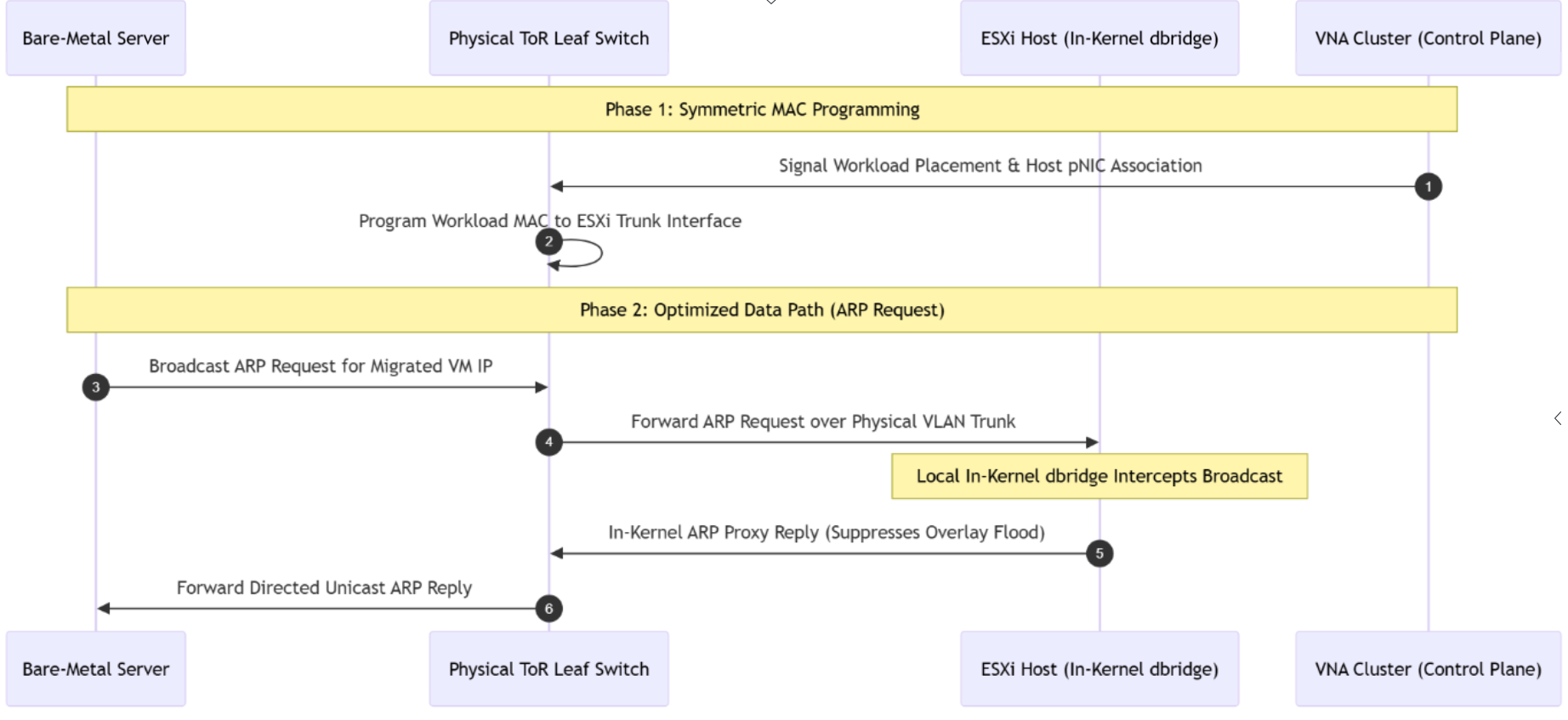
Step 1: Fabric Provisioning: The out-of-path VNA cluster tracks the placement of the migrated workload and pushes an orchestration update to the physical Top-of-Rack (ToR) switch fabric.
Step 2: Symmetric MAC Learning: The ToR leaf switch dynamically updates its hardware table, mapping the VM’s MAC address directly to the hosting ESXi physical trunk interface (pNIC). This establishes immediate symmetric routing.
Step 3: Target Broadcast: A physical bare-metal server sends an standard L2 broadcast ARP request over the network searching for the migrated VM’s IP address.
Step 4: Hypervisor Ingestion: The physical ToR switch forwards the broadcast frame over the designated physical VLAN trunk port directly into the ESXi host.
Step 5: ARP Suppression & Proxying: Instead of flooding the request into the overlay network, the host-local dbridge module intercepts the frame. Because the VNA already synchronized the MAC-to-IP bindings, the host kernel proxies the request and generates an authoritative ARP reply instantly.
Step 6: Directed Unicast Forwarding: The ToR switch receives the clean, proxied ARP reply as a directed unicast frame and forwards it back to the originating physical server, completely suppressing network-wide overlay flooding.
The Implementation Runbook
Phase 1: Fabric-Level Distributed VLAN Mapping
Capture 1: –

- Click On Networking.
- Click on VPC Connectivity.
- Click on External Conenctions.
- Click on ADD External Connection.
Capture 2: –
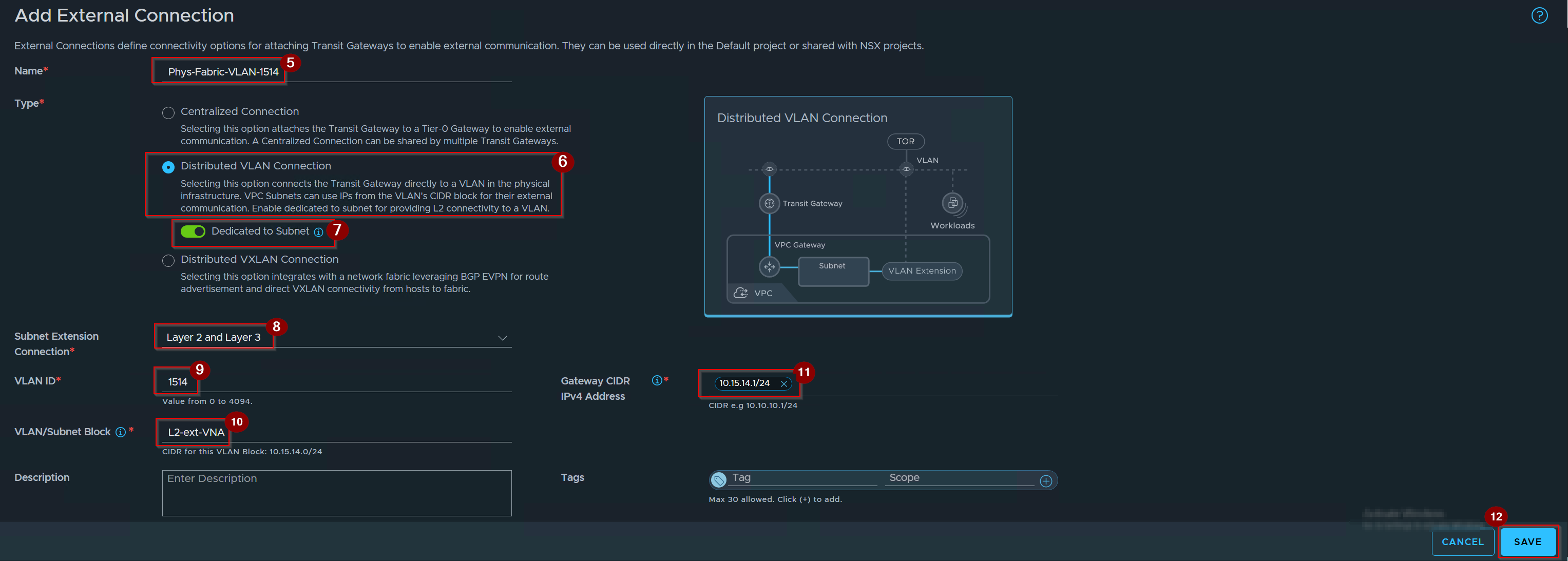
5. Give the name of external connection.
6. Click on Radio button of distributed Vlan Connection.
7. Enable the toggle button of Dedicated to Subnet.
8. Select the subnet extension connection.
9. Give the VLAN ID.
10. Give the VLAN/Subnet block.
11. Give the Gateway CIDR.
12. Click on Save.
Capture 3:-

Validation: -External Connection is successfully created.
Phase 2: Project Bonded
Capture 1:-
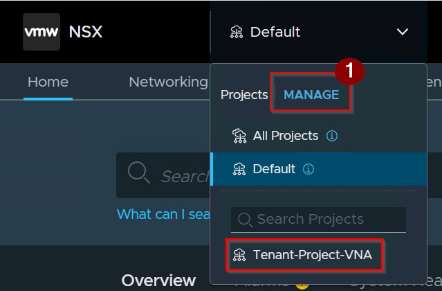
- Click on Manage.
Capture 2: –
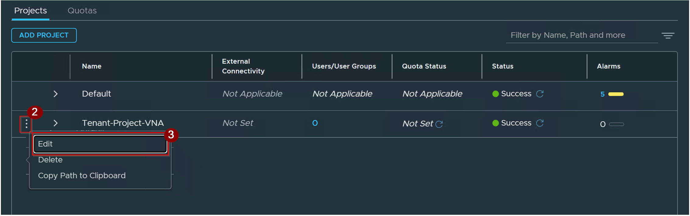
2. Click on 3 Dots.
3. Click on Edit.
Capture 3: –
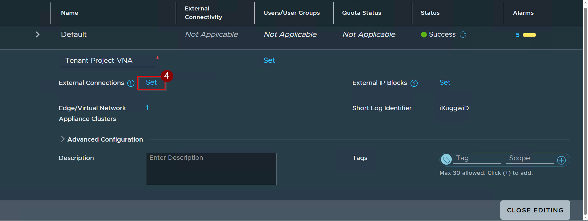
4. Click on Set after the External Connections.
Capture 4: –
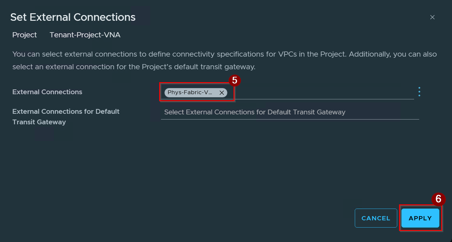
5. Select the External Connections.
6. Click on Apply.
Capture 5: –
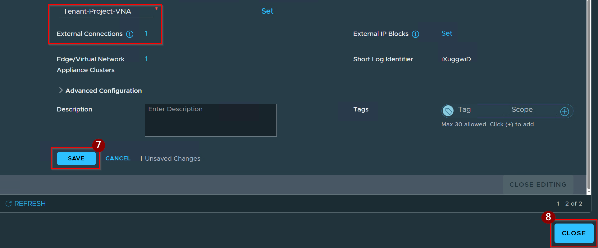
5. Click on Save.
6. Click on Close.
Capture 6:-
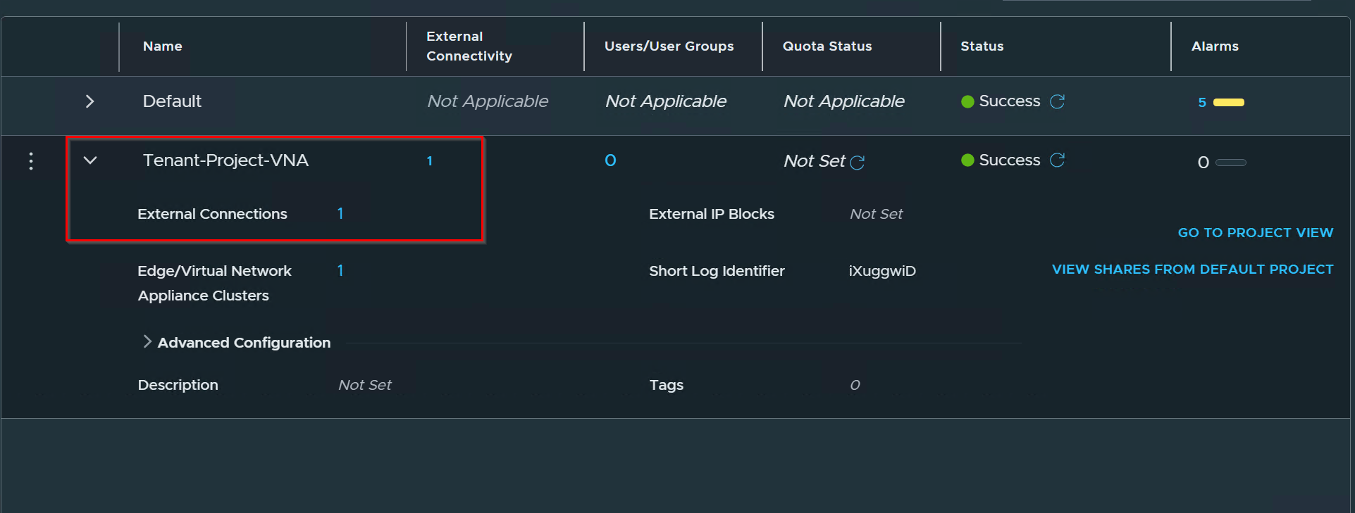
Validation: -External connection is successfully bonded in the project.
Phase 3: Tenant-Side Distributed Vlan TGW
Capture 1: –
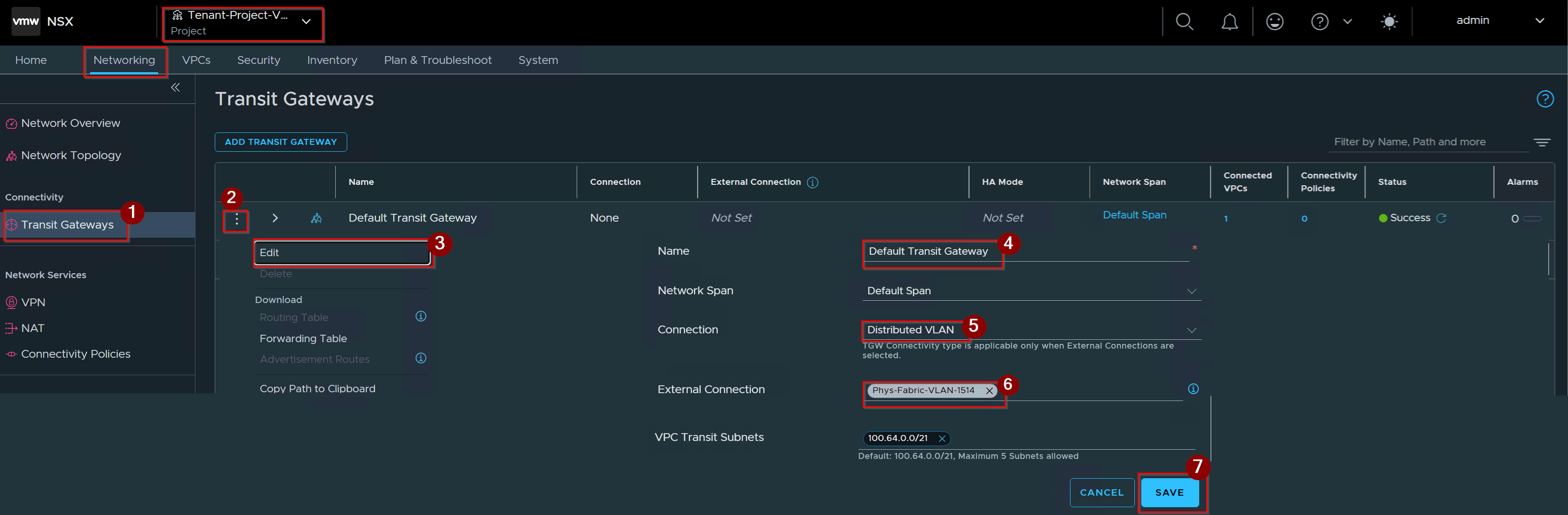
- Click on Transit gateway under connectivity.
- Click on 3 dots.
- Click on Edit.
- Give the Name.
- Select the Connection.
- Select the External Connection.
- Click on Save.
Capture 2:-

Validation: – Distributed VLAN TGW is successfully created.
Phase 4: Tenant-Side VPC Subnet Mapping
Capture 1: –
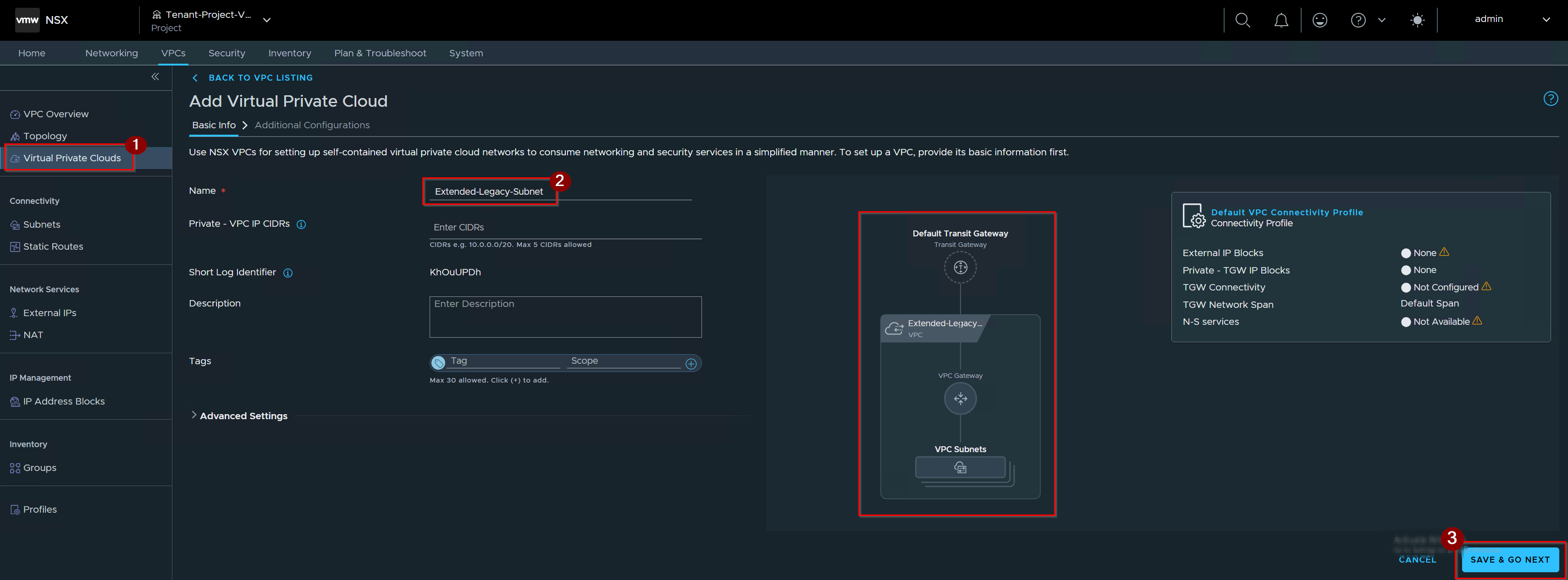
- Click on Virtual Private Clouds an navigate to Add VPCs.
- Give the name of VPC.
- Click on Save & GO NEXT.
Capture 2: –
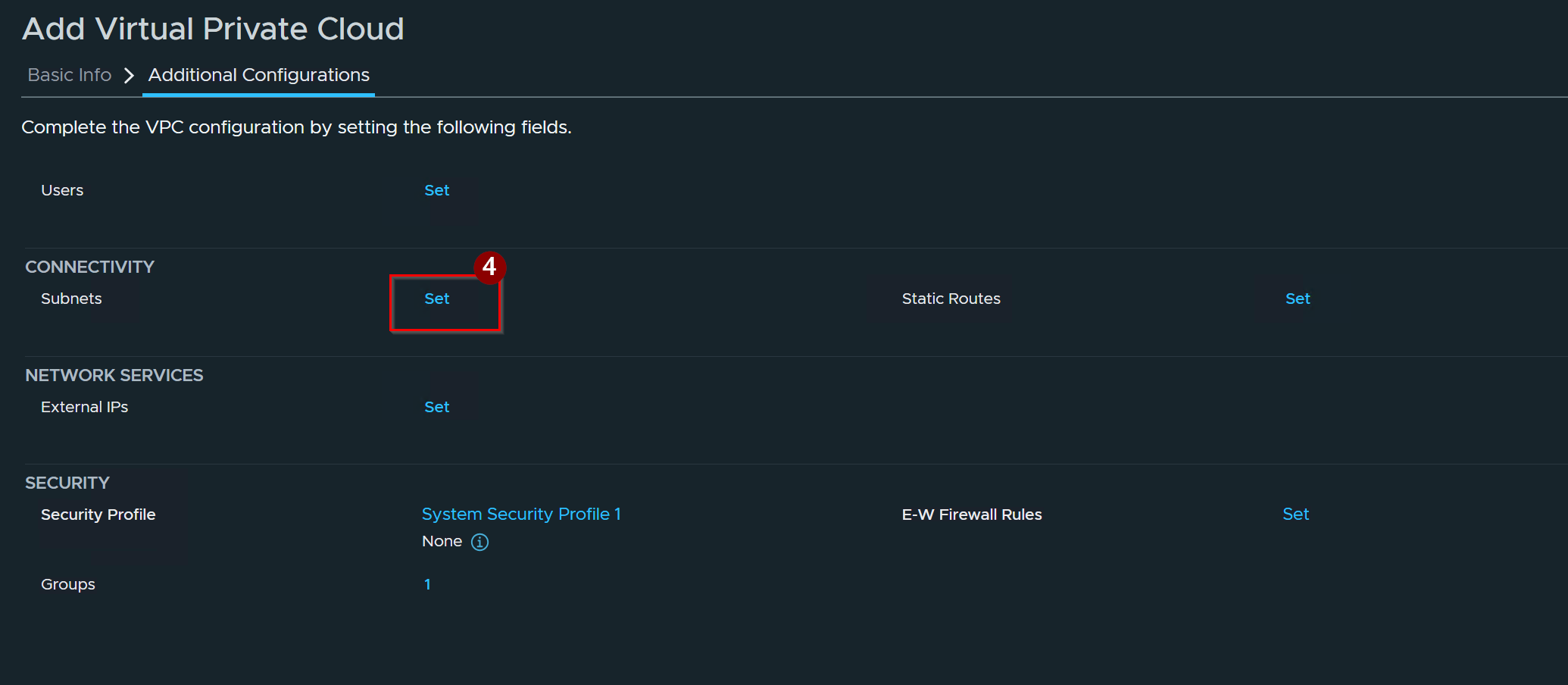
4. Click on Set in front of Subnets.
Capture 3:-
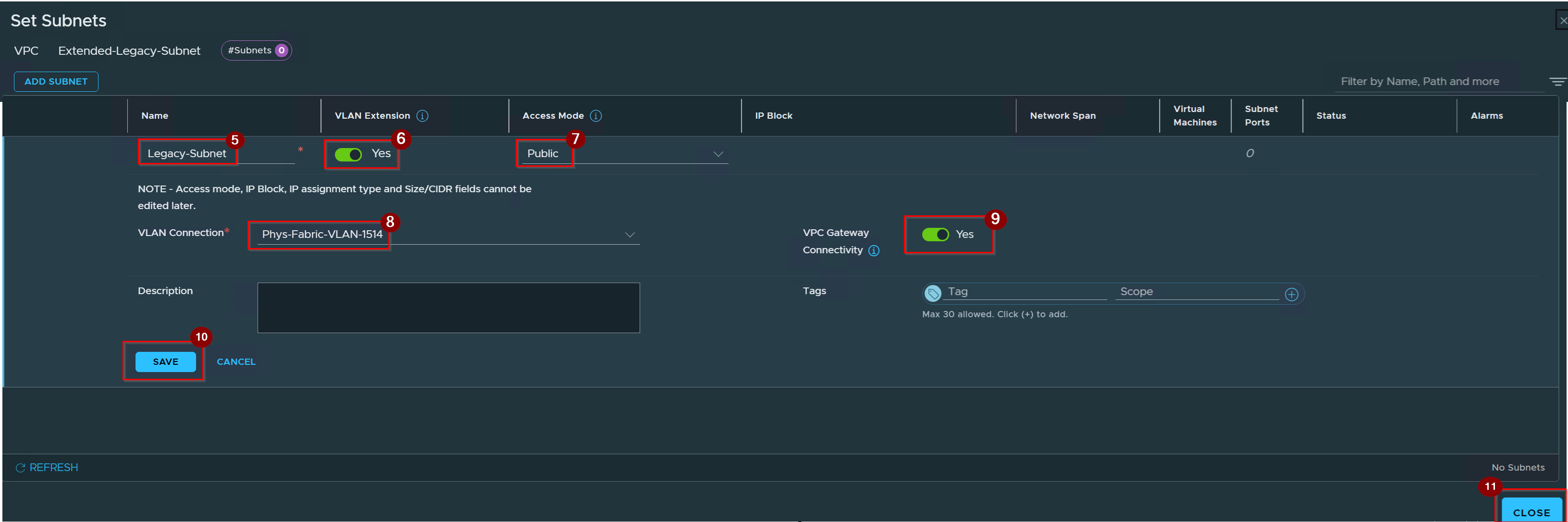
5. Give the Name of Subnet.
6. Enable the toggle of Vlan Extension.
7. Select the Access Mode Public.
8. Select the Vlan Connection.
9. Enable the VPC Gateway Connectivity.
10. Click on Save.
11. Click on Close.
Capture 4:-
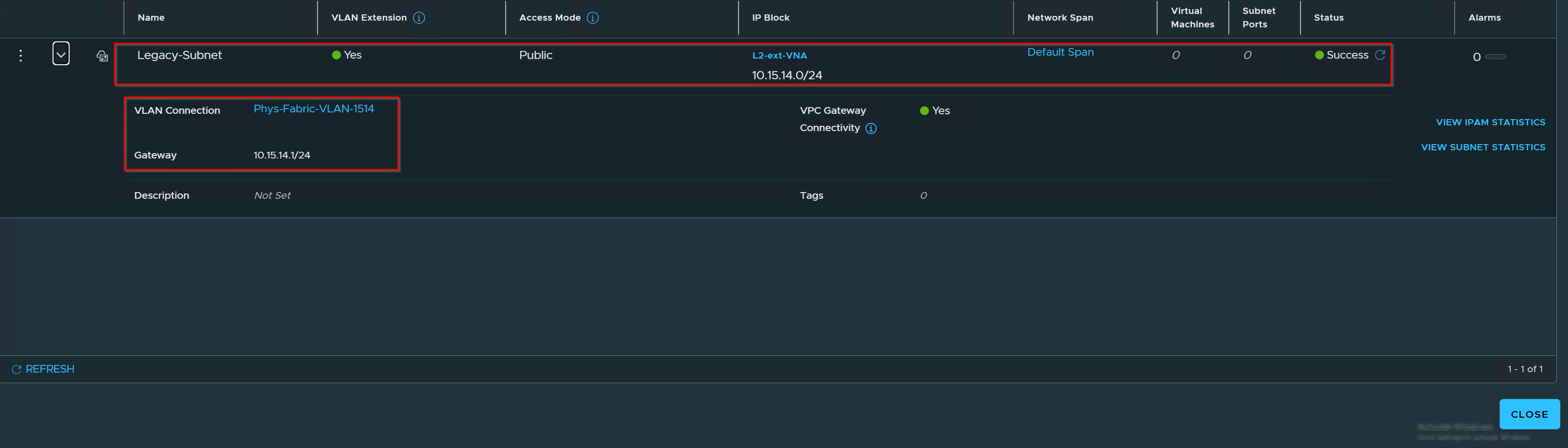
Validating the VPS is successfully created.
Phase 5: Workload Port Group Onboarding
Capture1: –
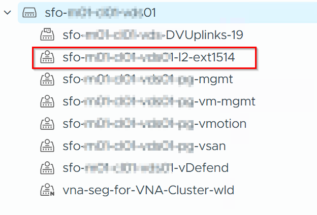
Create the DVPGs for Physical Vlan 1514.
Capture 2: –

Commit the configuration and power on the workload. The vNIC attachment triggers an interface binding notification, forcing the VNA to dynamically instantiate the operational database records and plumb the hypervisor transport plane.
Day-2 Operations: CLI Verification
- Querying the VNA Appliance Control Plane Shell
Capture 1:-
Dump all synchronized NSX policy paths to verify project-level inheritance

cmd :- get vpc-policy-paths
Capture 2: –
Discover the UUID of the active tenant VPC managed by this VNA

cmd :- get vpcs
2. Verifying the Host-Local Kernel State via ESXi nsxcli
Capture 1: –
Query the host to verify active distributed L2 extension bindings

cmd : – get subnet-vlan-extension
Capture 2: –

cmd: – get subnet-vlan-extension mac-table
Note: -This provides clear data-plane validation by displaying the active translation layer. It shows overlay workloads as static entries locked to their software PORT ID and overlay VNI , while simultaneously showing legacy underlay workloads dynamically learned over the physical host Uplink ports matching the correct physical VLAN tag.
Capture 3: –
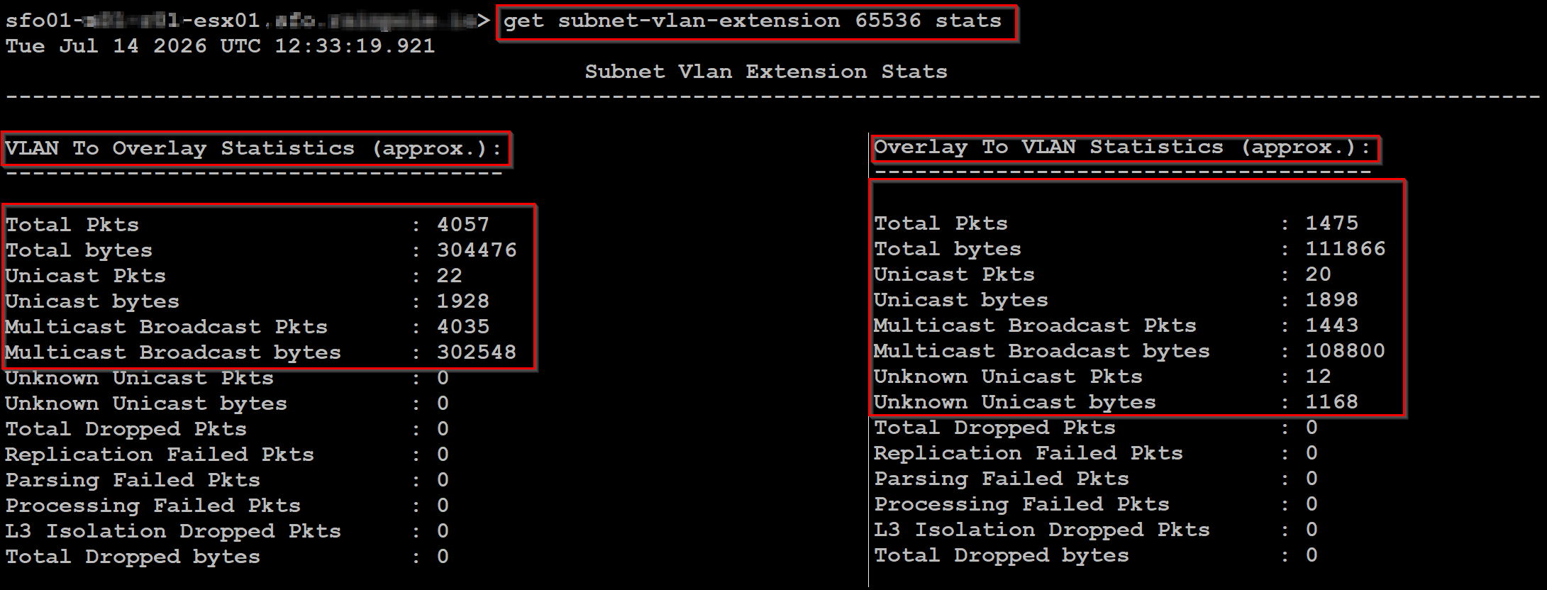
cmd : – get subnet-vlan-extension VNI stats
Pull real-time, directional data-plane performance counters.
Note:- Provides granular troubleshooting diagnostics by splitting performance counters into VLAN-to-Overlay and Overlay -to-VLAN traffic flows. This allows engineers to track total packets/bytes, verify broadcast distribution ratios, and verify that error matrices (like Parsing, failed or L3 isolation Dropped) sit at a clean 0
3. Correlating MAC Tracking on the Fabric
Capture 1: –
Visual Data Plane Tracing via NSX Traceflow
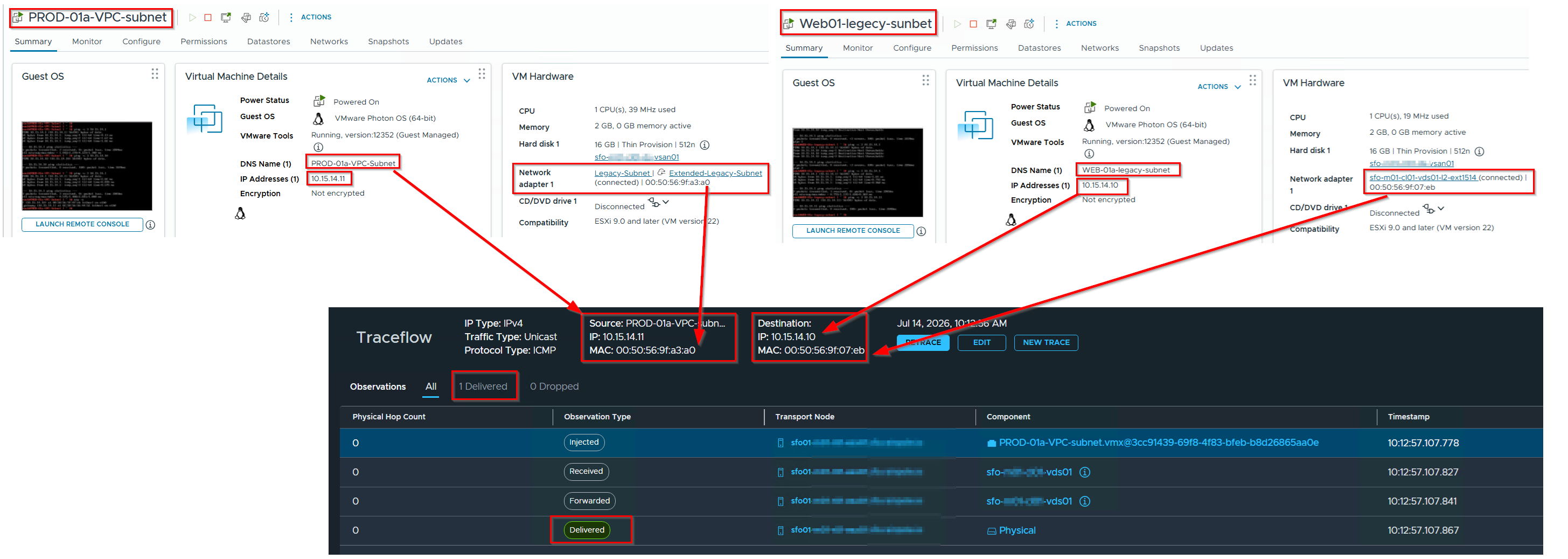
Note: – The Verification Trace Path: Running the Traceflow operation yields a clean 1 Delivered status. The hop observations demonstrate the execution precision:
Delivered (Physical): The host intercepts the packet and immediately forwards it out the local Uplink physical ports as a standard unicast frame.
Injected: The packet introduces into the logical segment module.
Received / Forwarded: The local hypervisor vSwitch maps the translation rules.
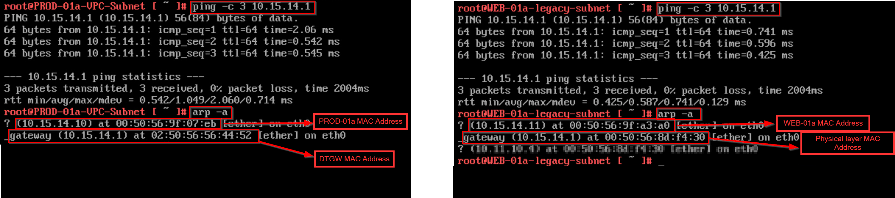
Capture 2: –
Guest OS Verification: End-to-End Datapath & ARP Resolution
Conclusion
The integration of VNA-driven VLAN Extensions for VPC Subnets inside VCF 9.1 changes how enterprise infrastructures handle hybrid network states. By moving from centralized, edge-anchored hardware bridging to an in-kernel distributed bridge (dbridge) architecture, the platform removes traffic bottlenecks and resource waste.
This model allows network operations teams to bridge legacy physical segments and modern multi-tenant VPC overlays at true hardware line-rate. The software-defined layer handles control plane orchestration completely out-of-path, allowing enterprise teams to execute zero-downtime, Zero-ReIP migrations without introducing structural risk or performance limits into the core physical network fabric.
 Puneet Sharma
Leave a comment